- Introduction
- Student Sense Hat Specifications
- Student Sense Hat Electronic Design Files
- Student Sense Hat Assembly
- Student Raspberry Pi Image Creation and Test Code
- Enterprise Wi-Fi
This stackable interface board for the Broadcom development platform also known as the Raspberry Pi is of a hand solderable design meant to be compatible with the devices in the Humber Parts Crib which require more skills and techniques to assemble. It has a bidirectional LED and three I2C device sockets. The bidirectional LED allows the hardware equivalent of "Hello World" to be achieved by blinking the LED. I2C is a very common hardware peripheral bus and is designed to have an analog breakout board, a Real Time Clock module, and an integrated environmental sensor module connected. It takes most individuals about a week of effort to complete these build instructions directed towards technologically inclined students especially given other commitments. Be aware that the image creation steps take at least 3 hours alone.
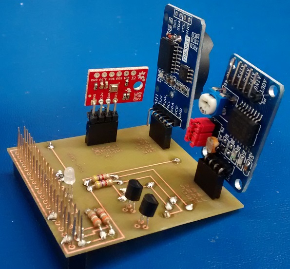
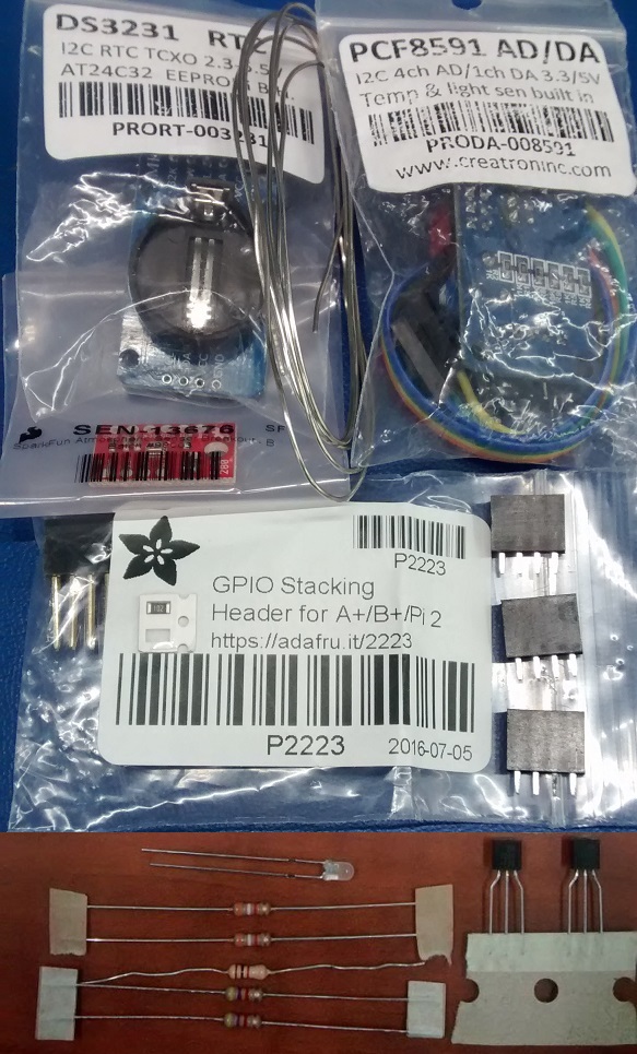
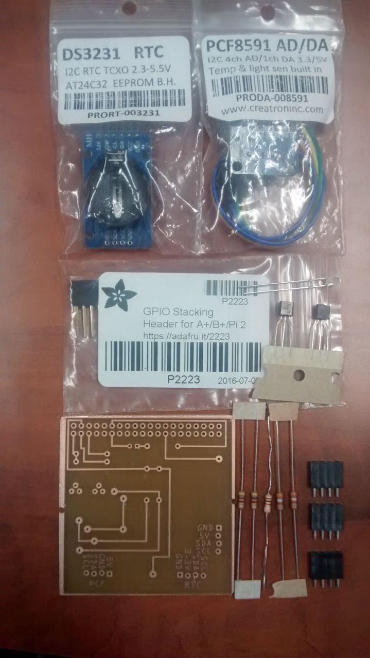
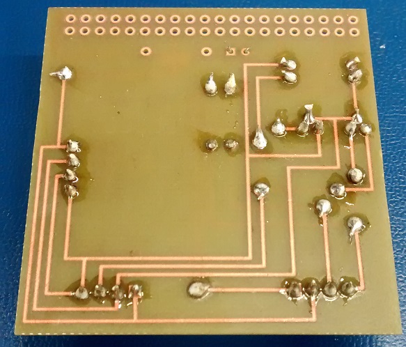
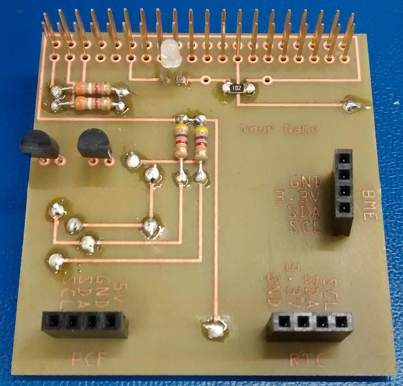
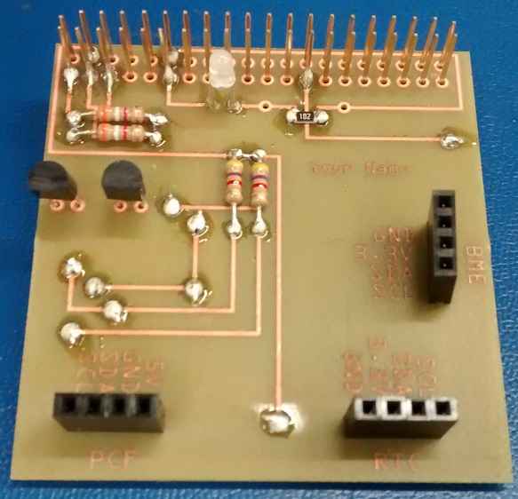
NOTE: This mostly through hole design is pin compatible with original mostly surface mount sense hat design which is on the devices in the Humber Parts Crib. The Fall 2017 design is in Fritzing while the Fall 2016 design was in Eagle, if curious, take a look at using the Sparkfun Cam file. Once you have recieved your PCB the kit looks something like the following photo.
For a list of materials please download the Excel file in the repository.
The more interesting components consist of:
-
1 bidirectional LED
-
DDS3231S IC RTC Clk/Calendar I2C 16-SOIC http://www.amazon.com/Donop-DS3231-AT24C32-precision-Arduino/dp/B00HCB7VYS
-
4 channel 8 bit a/d, 1 channel d/a PCF8591T I2C-Bus D/A CONVERTER http://www.modmypi.com/raspberry-pi/breakout-boards/seeed/raspberry-pi-adda-expansion-board https://www.creatroninc.com/product/pcf8591-8-bit-i2c-adc-dac/
-
Temperature, humidity, pressure sensor. SparkFun Atmospheric Sensor Breakout
-
One optional surface mount resistor.
-
Humber sense hat eeprom for i2c id <https://www.sparkfun.com/products/525 https://www.adafruit.com/product/1895\>
-
16 I/O pins MCP23017SO I/O Expander I2C https://www.adafruit.com/products/732
-
Breadboarding area
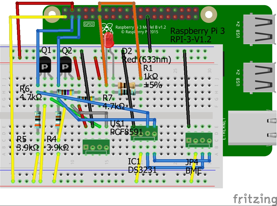
- The Fritzing file is available here: https://github.com/six0four/StudentSenseHat/tree/master/electronics/StudentSenseHatV06.fzz
- It has a breadboard view:
 Following the best practices:
This work is a derivative of "http://fritzing.org/parts/" by Fritzing, used under CC:BY-SA 3.0.
Following the best practices:
This work is a derivative of "http://fritzing.org/parts/" by Fritzing, used under CC:BY-SA 3.0. - It has a schematic view:
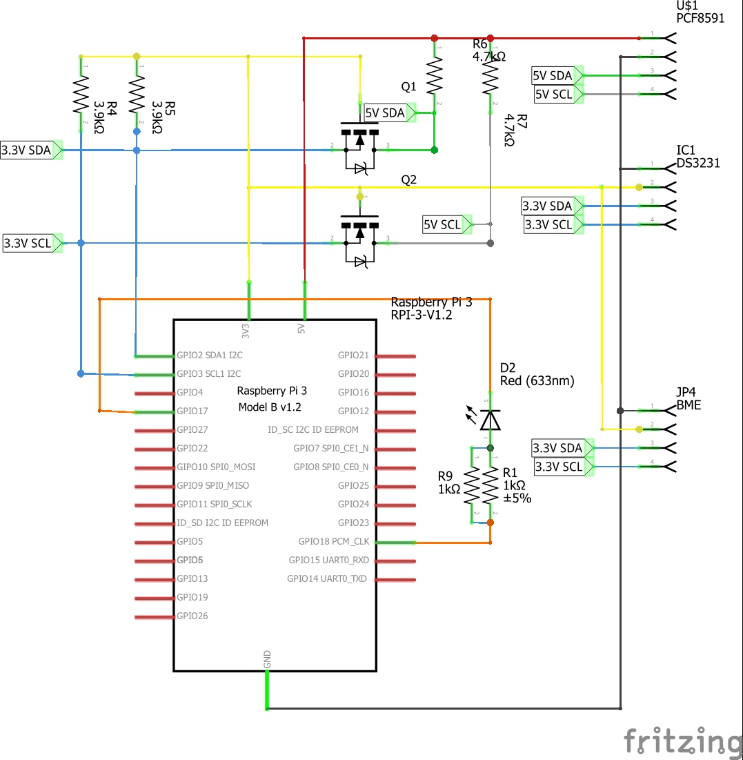 This work is a derivative of "http://fritzing.org/parts/" by Fritzing, used under CC:BY-SA 3.0.
 - It has a PCB view:
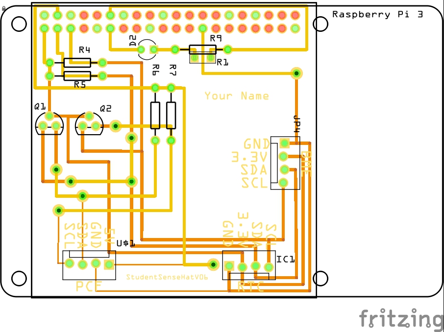 This work is a derivative of "http://fritzing.org/parts/" by Fritzing, used under CC:BY-SA 3.0.
 - A Bill Of Materials can be exported: BOM.
- As well as Gerber files: RS-274X.
- Please get started by ensuring that you have reviewed the six 15 second soldering videos and can comment on them. (If you are into materials, look up tin pest and tin whiskers.)
- Work through as much of this set of instructions as possible. (Feel free to drop through the Humber College Institute of Technology & Advanced Learning North Campus Prototype Lab in J233 for additional guidance both before and after class.)
- For additional soldering guidance such as surface mount and desoldering:
- Watch some YouTube Videos.
- Be sure to wear safety glasses and consult an expert regarding safety, you can even start at your local hackerspace (Ideally working towards IPC J-STD-001 Requirements for Soldered Electrical and Electronic Assemblies).
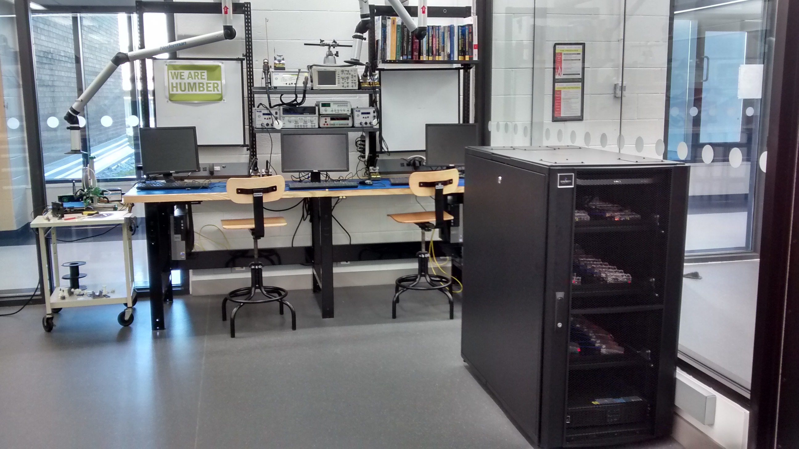
- Please remember your eyewear (safety glasses if you don't regularly wear glasses) and select a seat in J232.
- Turn on the computer under the desk on the left side.
- Note the red power switch to the back right side of the workstation that controls the power to the monitor, overhead light, and test equipment.
- Also note the under desk grounding strap jack for wrist straps - Electronics (ELIC) students must buy the $4.99 wrist straps while both CENG and ELIC students are to have the $4.99 safety glasses.
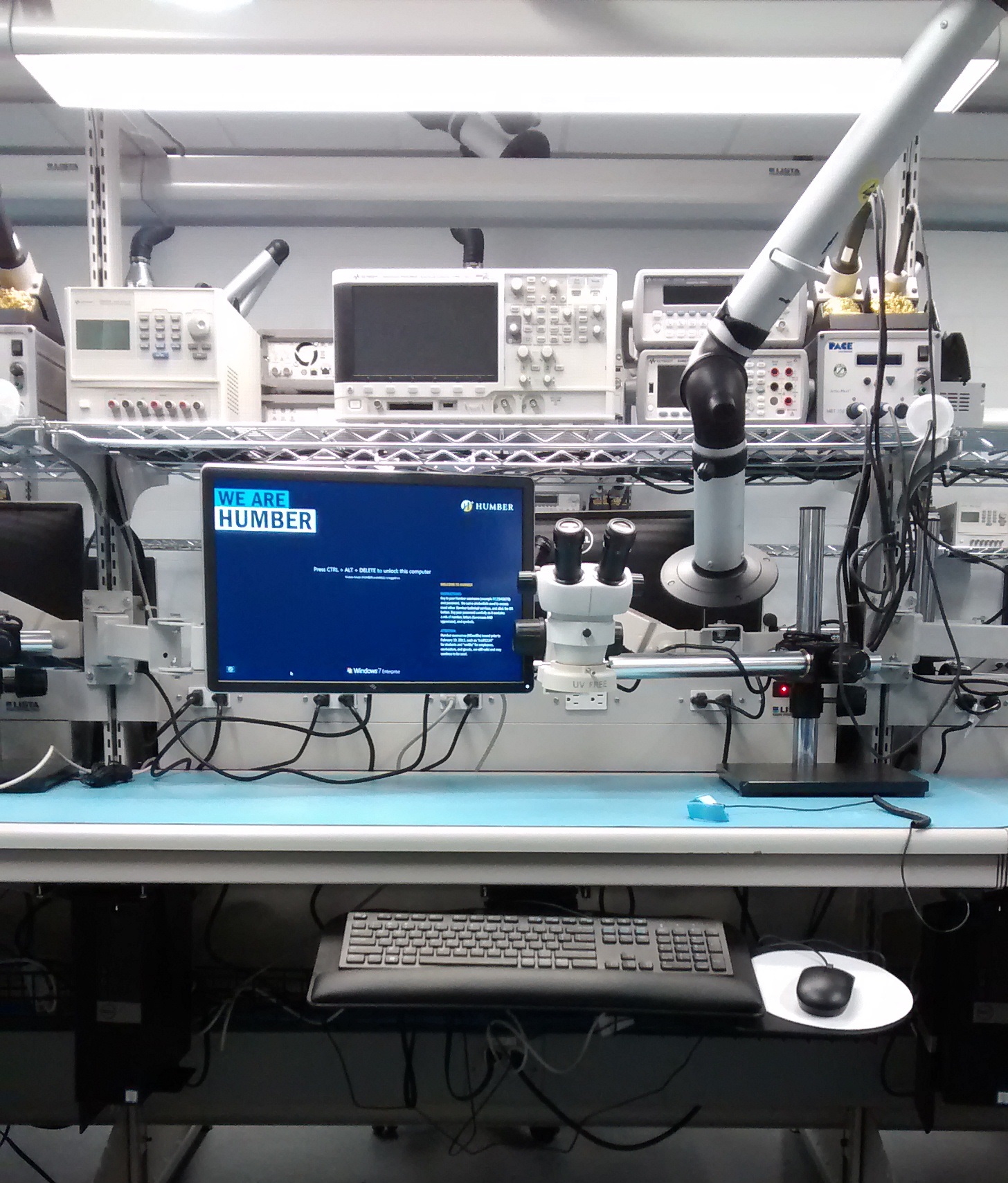
- When soldering move the extraction arm flow control towards the straight through symbol as it is in the photo below.
- The sponge in the soldering station can be moistened at the sink in J233.
- Start with components kit:
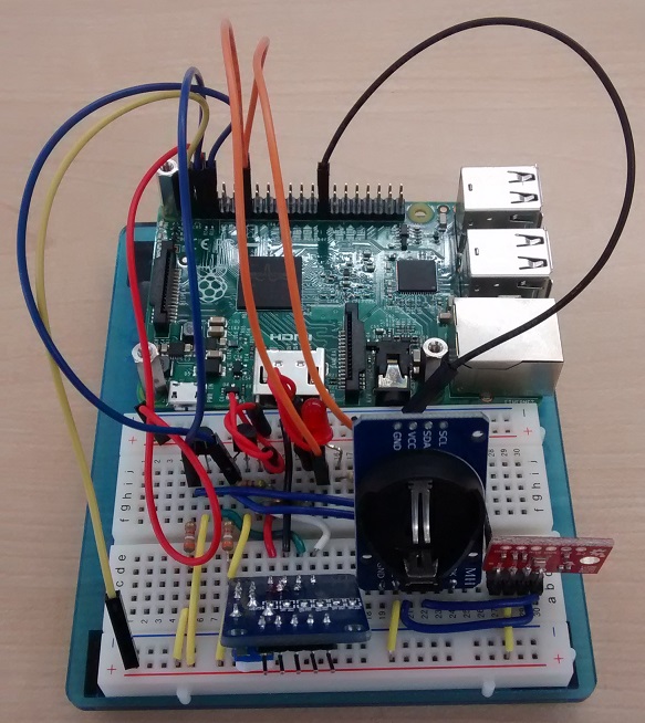
- Optional: try out your kit on your breadboard.
- Create schematic.
- Create board add photos of equipment and guide from 555 timer/prototype lab bb/plab I drive.
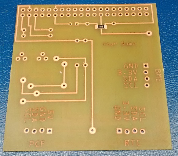
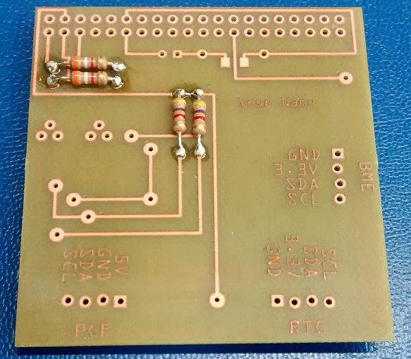
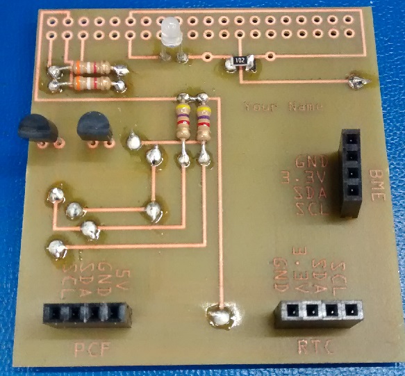
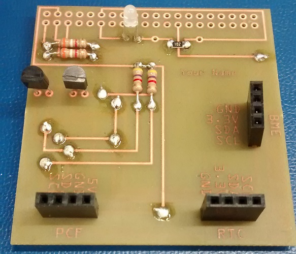
- At this stage you should have:
- Decide whether you will be attempting the optional surface mount resistor.
- Or whether you will be going with the through hole resistor.
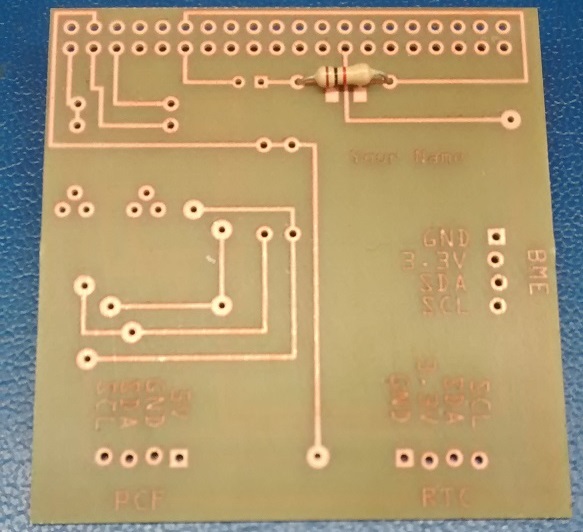
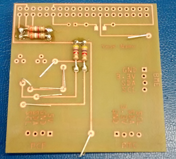
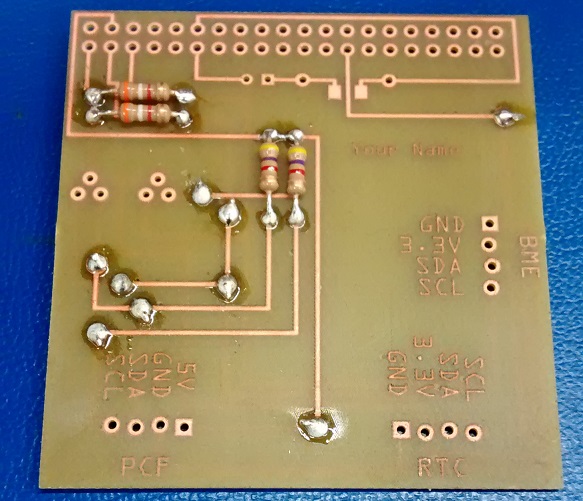
- Place resistors in corresponding locations:
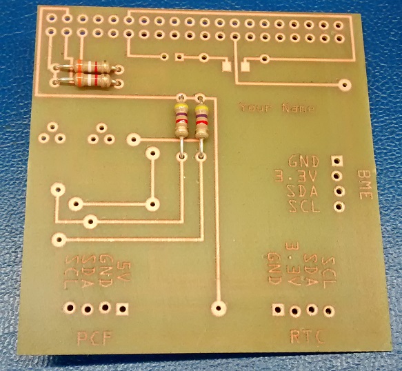
- Bend the leads to hold them in place.
- Solder the resistors from the bottom.
- Add flux if having trouble but, do not depress the end of the flux pen, just touching it is enough.
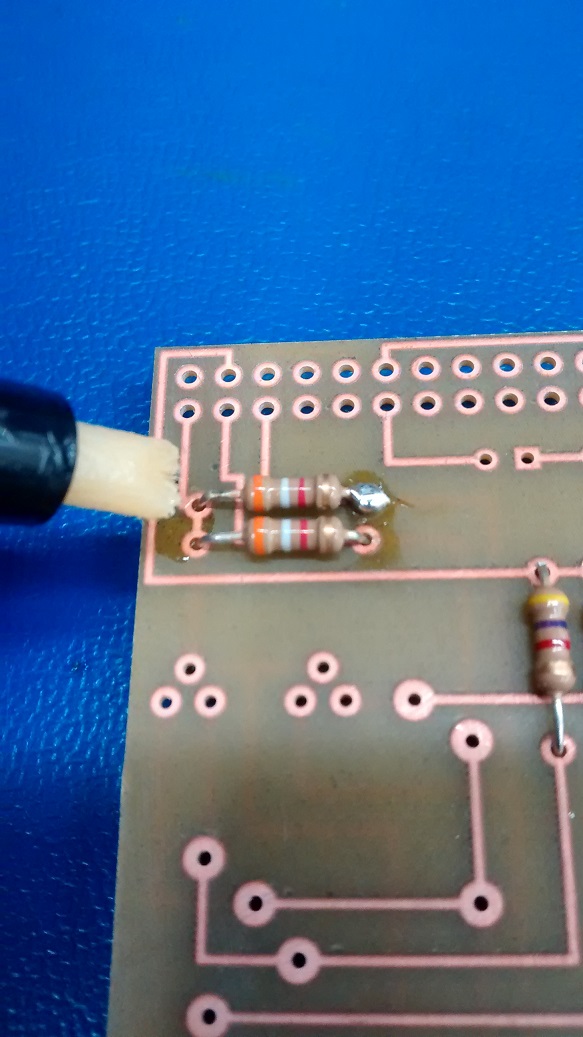
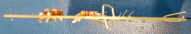
- Solder the resistors from the top.
- Trim and keep excess leads (hold onto them while cutting to not allow them to become projectiles).
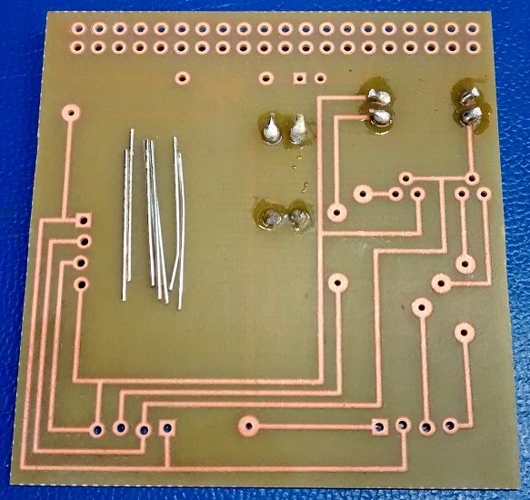
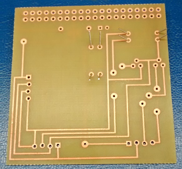
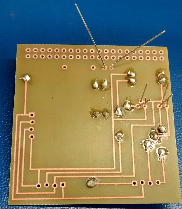
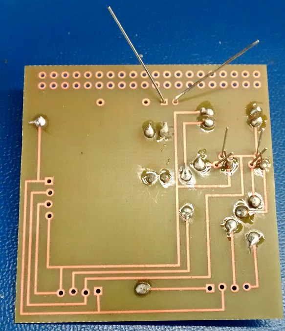
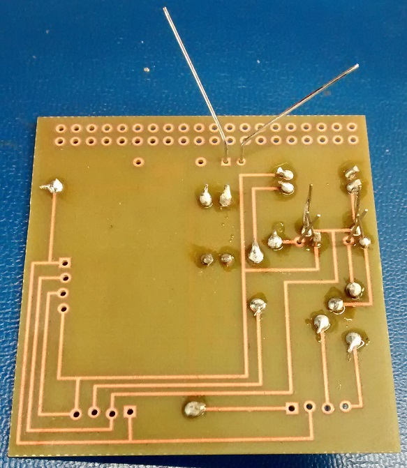
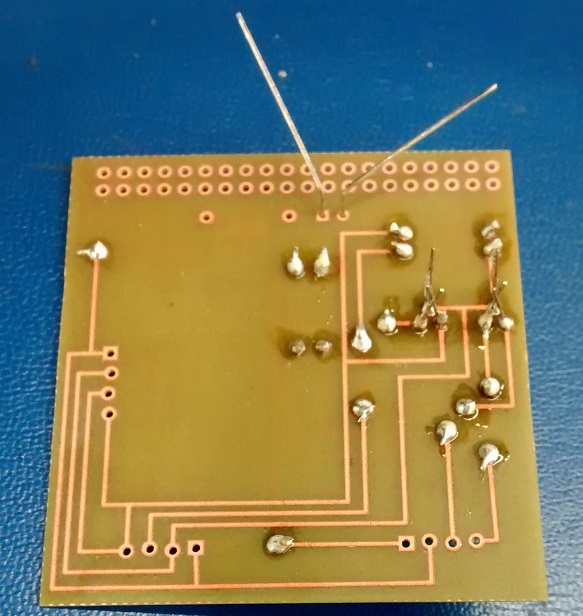
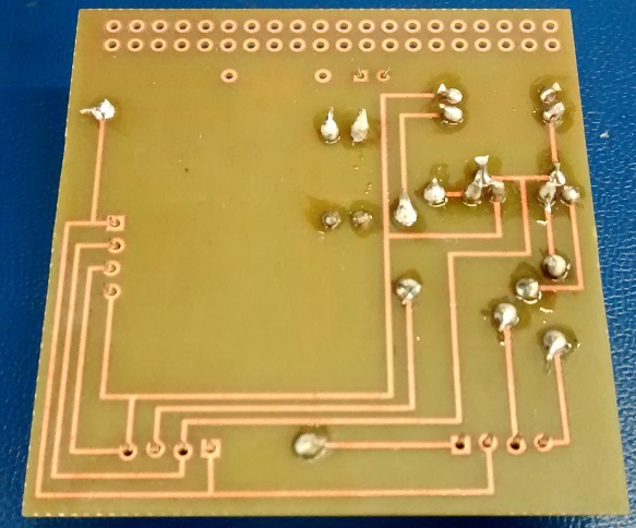
- Place via wires (can be stripped solid core wire or just leftover cut off resistor/LED leads) in corresponding locations:
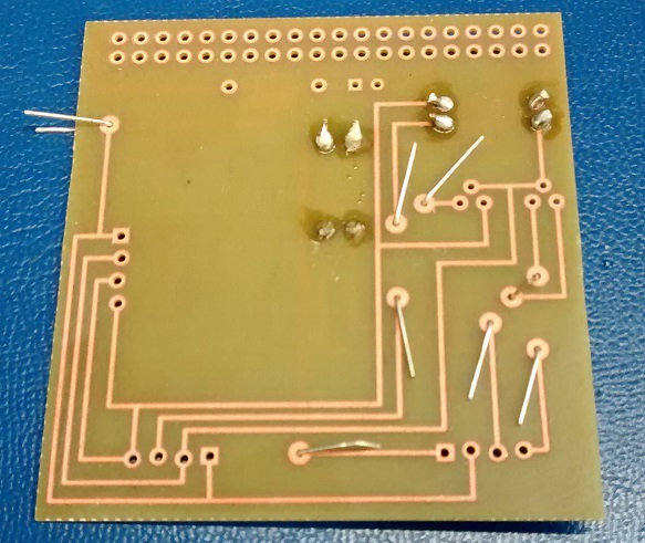
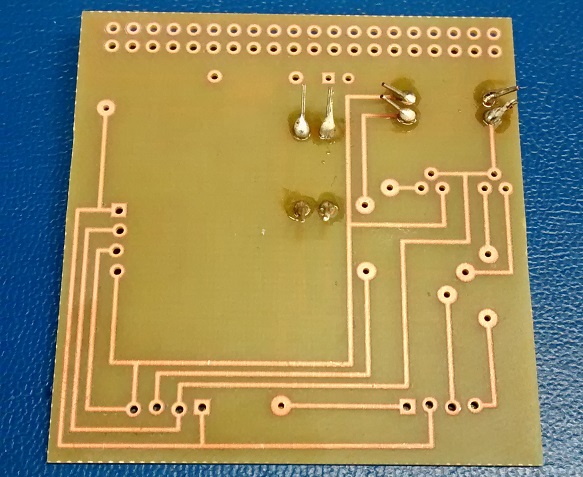
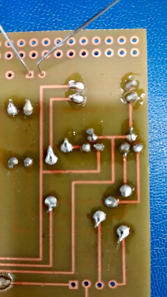
- Solder vias.
- Trim the excess via leads.
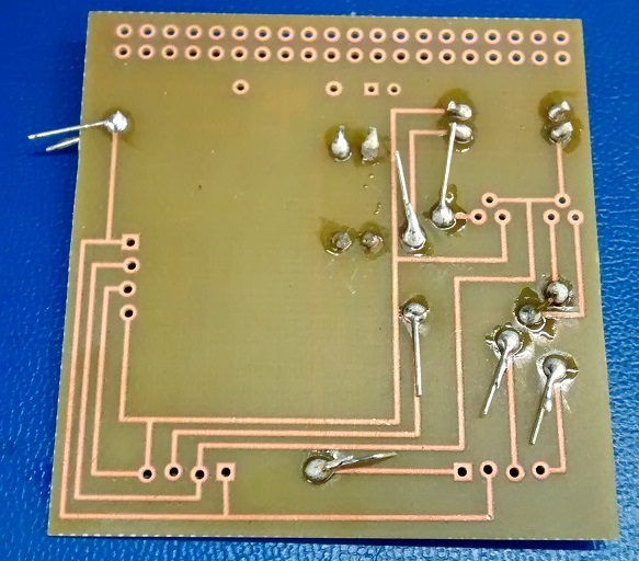
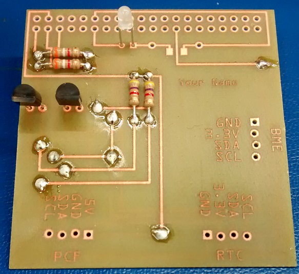
- Place MOSFETS and LED (N.B. the LED's longer leg is the same as on a red LED. Thus, when oriented the same way as the fritzing diagrams the red/green will be the opposite of those in the parts crib. Which way you put it is in your hands.)
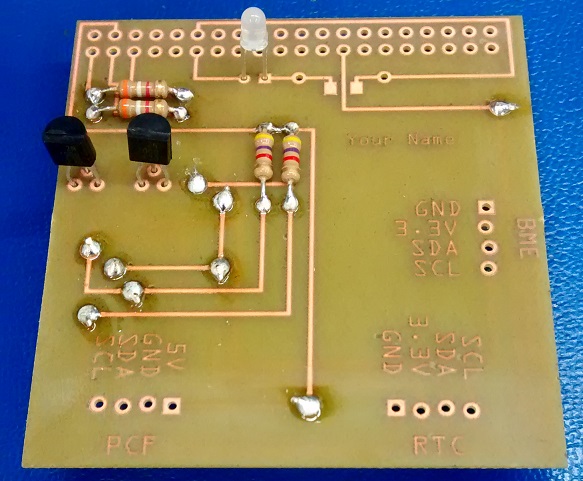
- Solder one pin of each MOSFET only from bottom side, semiconductor devices are heat sensitive.
- Solder another pin of each MOSFET only from bottom side.
- Solder the third pin of each MOSFET only from bottom side.
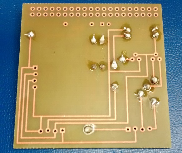
- Trim the MOSFET leads and make sure that none of them have solder bridges. (Note that the LED has shifted agianst the PCB here.)
- Make sure the LED is away from the PCB.
- Solder the LED only from the top side, semiconductor devices are heat sensitive.
- Trim the excess LED leads and use for any remaining vias.
- Place sockets.
- Solder sockets, no lead trimming is necessary.
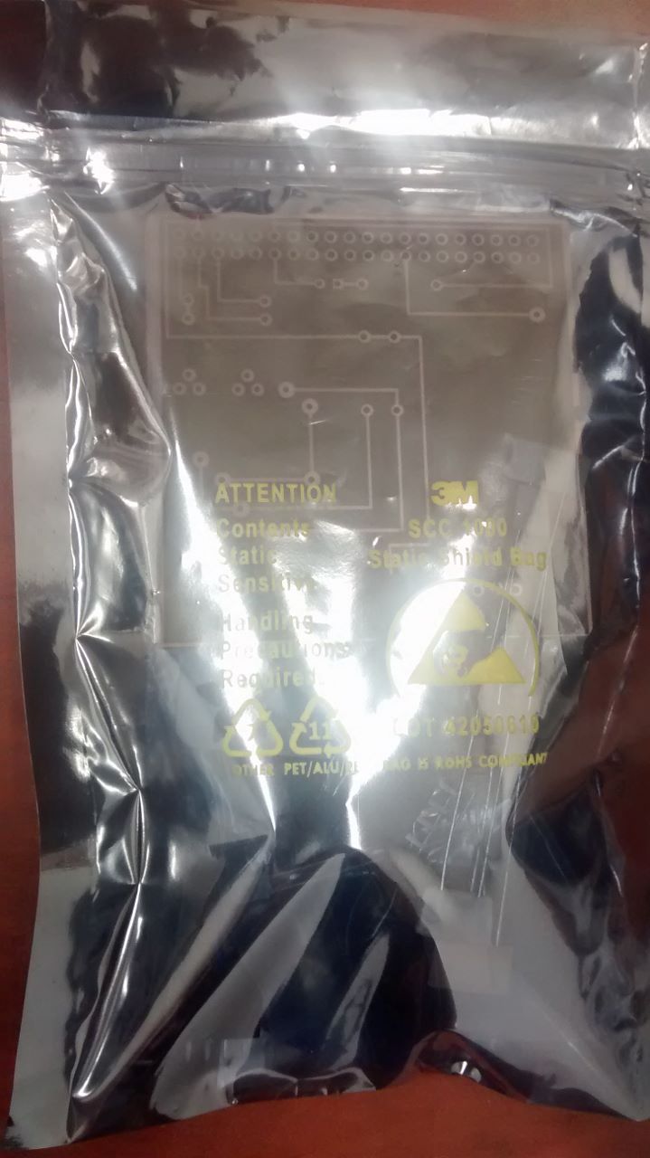
- If you soldered the through hole 1kΩ resistor into place then skip past the surface mount resistor steps. Else, if you did not solder the through hole 1kΩ resistor then remove surface mount resistor from its packaging.
- Note that the packaging may look empty from the back.
- Place a little bit of solder onto each of the pads, in this photo there is probably a little bit too much.
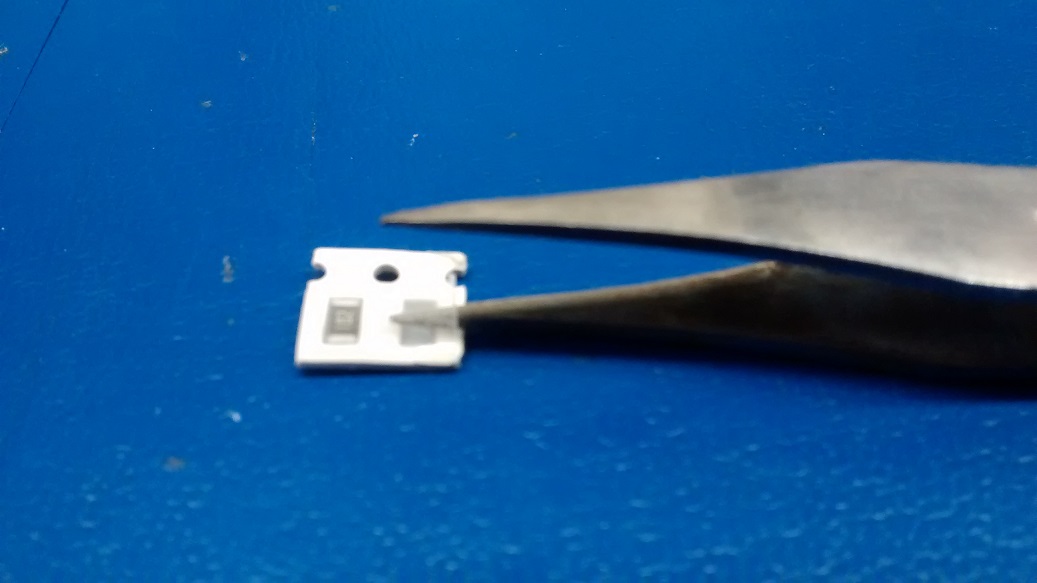
- Hold the suface mount resistor with tweezers and heat one end of the resistor with the soldering iron.
- It should now look something like this.
- Heat the other end of the resistor with the soldering iron so that it looks like the next photo.
- Continue to alternate reheating the ends to make it flush with the board.
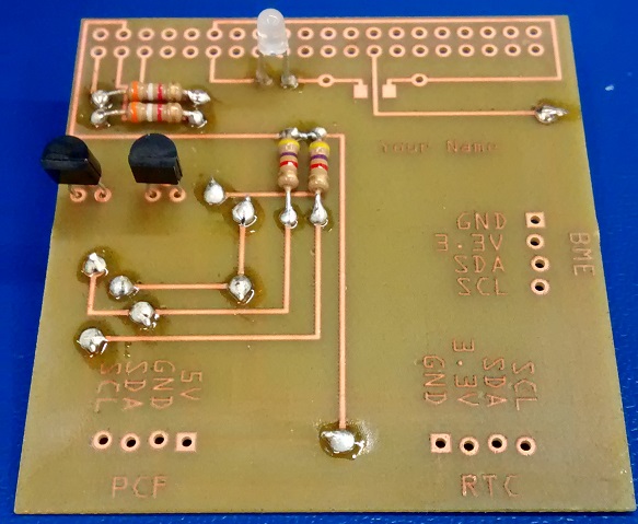
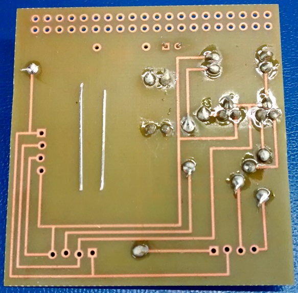
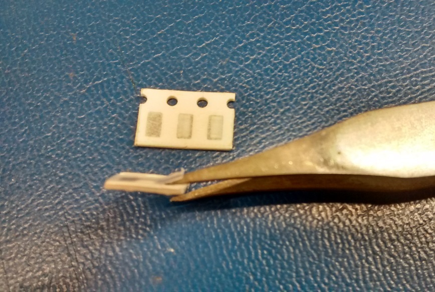
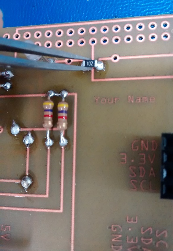
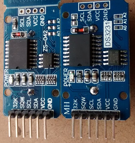
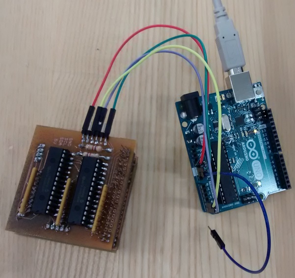
- While considering surface mount resitors, be aware that the RTC module can charge the CR2032 battery causing damage.
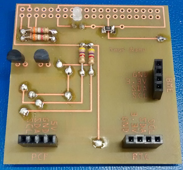
To permanently disable the charging circuit, please remove the 200 ohm surface mount resistor (board on left) near the unused I2C header by pushing it off the PCB (board on right) with a hot soldering iron.
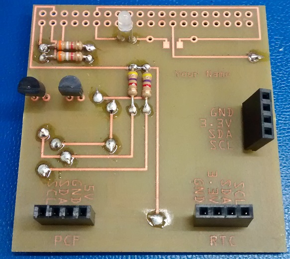
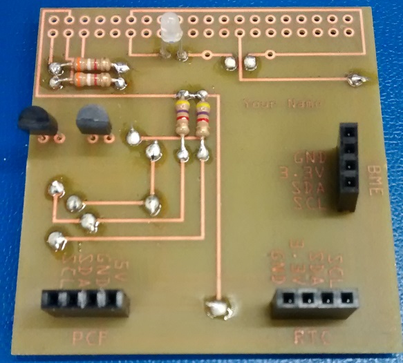
- Place the stackable header into place.
- Solder only where necessary.
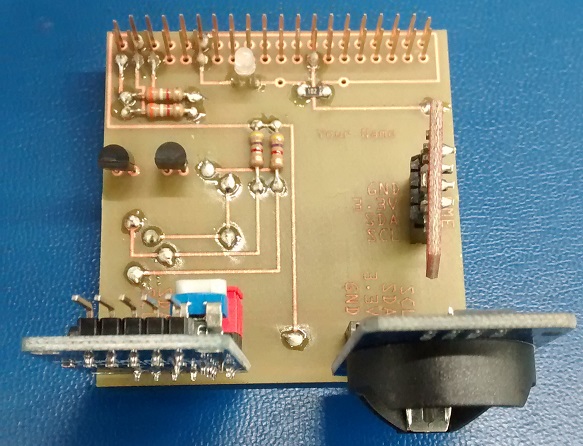
- Place the breakout board modules into their appropriate sockets adding headers as necessary.
- Be sure to clean up your workstation with the brush and dustpan.
- Test assembled hat on Vlad's test fixture (and ideally following IPC-A-610 Acceptability of Electronics Assemblies).
SenseHatTester
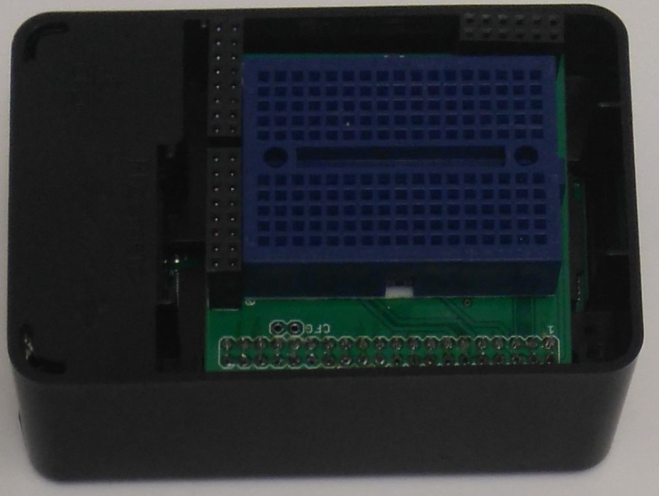
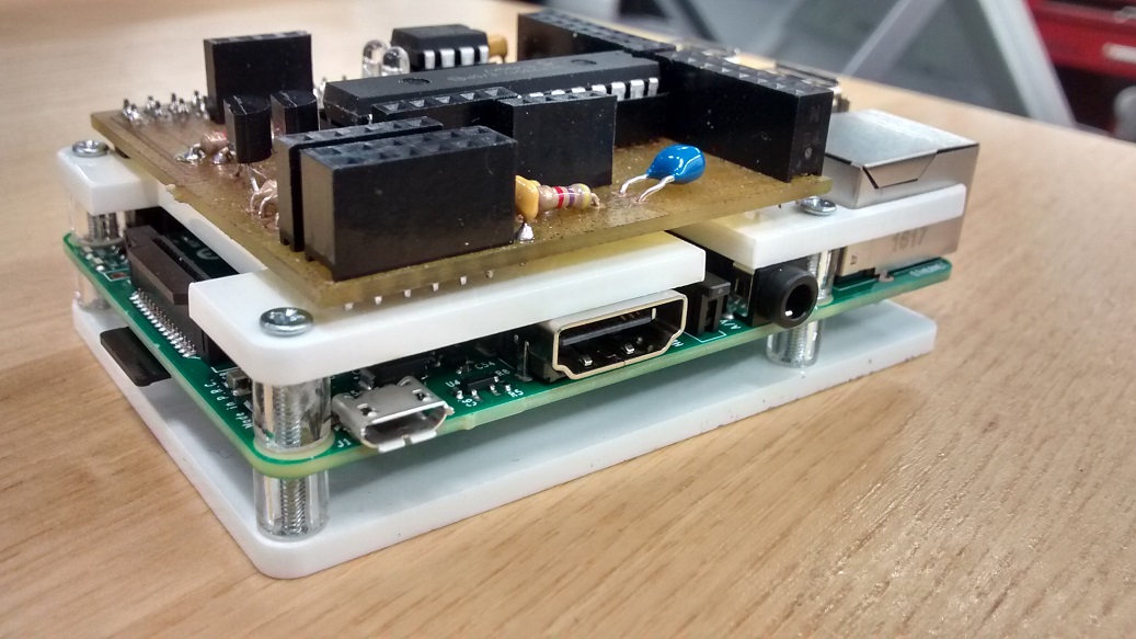
- Use CorelDRAW X6 and laser cutter to create a case guide from plab bb.
- Tap holes.
- Mount device.
-
Building the Humber image for the Sense Hat: https://github.com/six0four/StudentSenseHat/blob/master/cribpisdcard.md
Note that apt-get puts the installed packages into /var/cache/apt/archives/ so a zip of the files from there would complement the script used by these instructions. -
Open a terminal and type:
git clone https://github.com/six0four/StudentSenseHat.git
cd StudentSenseHat/firmware
gcc -Wall -o traffic2B traffic2B.c -lwiringPi
sudo ./traffic2B
write to your blog what happens with your LED.
-
From the Start Menu->Preferences->Raspberry Pi Configuration->Interfaces set I2C to Enabled.
-
Return to your terminal and type:
make
sudo ./ghmain
write to your blog what happens.
-
You can read the OS date with:
date
You can set the OS date with:
sudo date –s “29 AUG 1997 13:00:00”
You can write the OS date to the RTC with:
sudo hwclock –w
You can read the RTC date with:
sudo hwclock -r
-
Things to consider for your particular application: boot options (Gui to terminal), and permissions when auto mounting usb keys.
-
Use http://sourceforge.net/projects/win32diskimager/ to read the image into a file.
Connecting to Enterprise Wi-Fi can be a challenge but the graphical desktop has come a long way from where it was, please share your respective successes in situations where the GUIs do not work - here is my configuration:
-
In /etc/network/interfaces:
auto lo iface lo inet loopback iface eth0 inet dhcp allow-hotplug wlan0 iface wlan0 inet manual wpa-roam /etc/wpa_supplicant/wpa_supplicant.conf iface default inet dhcp -
In /etc/wpa_supplicant/wpa_supplicant.conf:
ctrl_interface=DIR=/var/run/wpa_supplicant GROUP=netdev
update_config=1
network={
    ssid="myWi-Fi@Humber"
    proto=RSN
    key_mgmt=WPA-EAP
    pairwise=CCMP
    auth_alg=OPEN
    eap=PEAP
    identity="n12345678"
    password="aaaAAA12"
    phase2="auth=MSCHAPV2"
}
I have been told that more recently the Prototype Lab staff have said to use:
sudo nano /etc/wpa_supplicant/wpa_supplicant.confAdd the follow to file and fill in identity and password field save and restart RPI:
network={ ssid="myWi-Fi@Humber" priority=999 proto=RSN key_mgmt=WPA-EAP pairwise=CCMP auth_alg=OPEN eap=PEAP identity="STUDENT ID" password="PASSWORD" phase1="peaplabel=0" phase2="auth=MSCHAPV2" } -
Download Humber Certificate (For HumberSecure).cer from https://its.humber.ca/wireless/humbersecure/
-
Reboot
