Comments (91)
 kipper2k
commented on August 31, 2024
2
kipper2k
commented on August 31, 2024
2
Here is a picture of the underside of the Rev3 A500. The yellow wires show what is needed to be done to get the HDMI working. Doing this means you do not need to modify the HDMI adapter.
Ignore the black wire mod, that was on this board already

from amiga-digital-video.
 hansliss
commented on August 31, 2024
2
hansliss
commented on August 31, 2024
2
For the A2000-A (rev. 4), and perhaps even A1000, it may be possible to do the same thing by patching U77 pin 8 to Denise pin 32, and pin 15 on the MMU slot through an inverter to Denise pin 34. I may test this after I've verified my adapters on an A500.
I got it working in my A2000-A! Instead of the MMU slot, I took CDAC from RN17 pin 3, through a 74*04 inverter and to pin 34 on Denise. My setup was a bit too precarious to keep (with a caseless PSU and cables everywhere) so I'll experiment further later, but it looked like a perfect picture.
There's a bit of a mess with the hot glue but I didn't want to risk anything coming loose. I'll add some Kapton tape on the case below this kludge just in case.


from amiga-digital-video.
kipper2k
commented on August 31, 2024
1
using this...
/CDAC, pin 34 on Denise, is available on Gary, pin 26 - Gary is U5, a 5719 near the center of the motherboard.
/CSYNC, pin 32 on Denise, is available on U41, pin 9 - U41 is a DIL-20 74HCT245 just next to Denise.
I followed traces to find better places to connect a pin header to.

the CDAC signal is tied into pin 26 of Gary, if you follow the trace down you will see there is a via just left of the capacitor, that is where i added the pin header. Same idea for the sync signal, i just followed it until i found a via to add a header there too.
The adapter board could be updated to break out pin 32 and pin 34 to a 2 pin header on the right side to allow an easier install on a Rev3 A500. Another option would be to remove the motherboard and add the 2 wires on the underside, then no changes to the adater board would be needed
from amiga-digital-video.
 c0pperdragon
commented on August 31, 2024
1
c0pperdragon
commented on August 31, 2024
1
@bkodenkt You could really try to swap the boards around. My guess is that something is not working correctly with your adapter/Pi in the non-working setup.
from amiga-digital-video.
kipper2k
commented on August 31, 2024
1
For the CDTV i just redone the shape of the a500 version. I done similar to this as to the A600, basically made a signal breakout board for denise and trnsferred them to the 20 pin FFC cable, the cable length is 30cms (1,0mm pitch)
i'll find some pics


The case closes fine. I redone it to fit on the right side plate at the back and made the left plate for joy/serial mouse/usb mouse and a500 keyboard input. ( imade a little error on the back pcb that i had to run a jumper.
Also you can see that i used a 32 pin ffc header as i didnt have a 20 pin one handy at the time but the boards are set up for 20 pin FFC cable. Picture quality is awesome! The final version has only the 20 pin FFC headers on the pcb.
The hdmi connectors from the Pi were bought from https://www.buyapi.ca/search.php?search_query=diy%20hdmi§ion=product
You don't need to buy the cable, any 20pin 0.5mm pitch cable will suffice.
I initially done this design with a 20 pin IDC through hole connectors. I got rid of them as there isn't enough space up top to close the case so only FFC is needed
from amiga-digital-video.
 bkodenkt
commented on August 31, 2024
1
bkodenkt
commented on August 31, 2024
1
I can confirm that @solarmon 's solution works with the CDTV and allows to close the case. The flexcable has to be routed left, down and then the RGB2HDMI/Pi0 need to be placed between CD drive back and the upper mainboard shielding. https://www.amibay.com/showthread.php?118201-solarmon-RGBtoHDMI-boards-(for-A600-and-A500-)
Mateusz Kowalski is selling angled adaptors on Facebook. These work fine in the CDTV as well. You might ask him for the source files: https://www.facebook.com/groups/CDTVUG/posts/4227475423977658/
from amiga-digital-video.
 solarmon
commented on August 31, 2024
1
solarmon
commented on August 31, 2024
1
I'm now testing a RGBtoHDMI solution for the CDTV that fits straight in to the video slot.


It works nicely, but needs some further minor design tweaks.
from amiga-digital-video.
 culexus8
commented on August 31, 2024
culexus8
commented on August 31, 2024
Do you get the OSD menu to pop up if you hold the switch that is connected to the adapter board?
from amiga-digital-video.
 IanSB
commented on August 31, 2024
IanSB
commented on August 31, 2024
If the board works in other revisions but the menu won't appear when you press the button, then the most likely cause is that the pixel clock is missing. This is generated from the CDAC line in "Denise" mode and the 7Mhz clock in "Super Denise" mode. Have you tried setting the link to Super Denise mode?
Can you check if those signals are present on the rev3 with an oscilloscope?
from amiga-digital-video.
kipper2k
commented on August 31, 2024
@IanSB thanks for info, i will try this later today...
edit,
i tried swapping the jumper and i ended up with the blinking... http://www.kipper2k.com/pics/rev3blinking.mp4
i tried changing pal/ntsc mode and reset the prefs back to default and no change
from amiga-digital-video.
IanSB
commented on August 31, 2024
i tried swapping the jumper and i ended up with the blinking
Blinking means the sync timings don't match those in the profile so something is different about the sync signal on your rev 3.
Your symptoms seem to match those that @hansliss is seeing with an A2000
See: #11
Can you post a photo of the source summary page in the info menu.
from amiga-digital-video.
hansliss
commented on August 31, 2024
i tried swapping the jumper and i ended up with the blinking
Blinking means the sync timings don't match those in the profile so something is different about the sync signal on your rev 3.
Your symptoms seem to match those that @hansliss is seeing with an A2000
See: #11Can you post a photo of the source summary page in the info menu.
I found schematics for the A500 in an "Amiga 500 Introduction" (https://museum.syssrc.com/static/Amiga_500_Introduction.pdf) that does indeed show both /CDAC and /CSYNC (pin 34 and 32) missing from the Denise socket. It doesn't say which revision they depict but it seems likely that it's an early one.
from amiga-digital-video.
hansliss
commented on August 31, 2024
i tried swapping the jumper and i ended up with the blinking
Blinking means the sync timings don't match those in the profile so something is different about the sync signal on your rev 3.
Your symptoms seem to match those that @hansliss is seeing with an A2000
See: #11
Can you post a photo of the source summary page in the info menu.I found schematics for the A500 in an "Amiga 500 Introduction" (https://museum.syssrc.com/static/Amiga_500_Introduction.pdf) that does indeed show both /CDAC and /CSYNC (pin 34 and 32) missing from the Denise socket. It doesn't say which revision they depict but it seems likely that it's an early one.
From what I can gather, on the A500 rev. 3, the missing signals are available so it might be possible to patch them in to the Denise socket - this is done entirely at your own risk, obviously. Find and double-check schematics first!
/CDAC, pin 34 on Denise, is available on Gary, pin 26 - Gary is U5, a 5719 near the center of the motherboard.
/CSYNC, pin 32 on Denise, is available on U41, pin 9 - U41 is a DIL-20 74HCT245 just next to Denise.
from amiga-digital-video.
kipper2k
commented on August 31, 2024
k, its working, i need to tidy it up and then i will show some pics etc
from amiga-digital-video.
hansliss
commented on August 31, 2024
For the A2000-A (rev. 4), and perhaps even A1000, it may be possible to do the same thing by patching U77 pin 8 to Denise pin 32, and pin 15 on the MMU slot through an inverter to Denise pin 34. I may test this after I've verified my adapters on an A500.
from amiga-digital-video.
kipper2k
commented on August 31, 2024
awesome, my a1000 is an NTSC version and i think it is different, the schematics are very poorly photocopied and i am having a hard time reading it. From what i can tell sync is on U7a pin 2 and cdac pin 15 of the 86 pin header
from amiga-digital-video.
hansliss
commented on August 31, 2024
awesome, my a1000 is an NTSC version and i think it is different, the schematics are very poorly photocopied and i am having a hard time reading it. From what i can tell sync is on U7a pin 2 and cdac pin 15 of the 86 pin header
Can you somehow send me the schematics you have, so I can compare them to the various schematics I've collected?
from amiga-digital-video.
kipper2k
commented on August 31, 2024
here is a link...
from amiga-digital-video.
hansliss
commented on August 31, 2024
here is a link...
Ah, yes. I saw that one. One of the worst ones.
You can find the uninverted CDAC on R107, on the side not connected via a nearby ferrite bead to pin 8 on U91 (looks like it might be a 74S51), and also of course on pin 15 on the expansion connector. It doesn't seem to go anywhere else.
/CSY is on Agnus pin 39 and on U6A (HC244) pin 8, which should be near Denise. The pin number is hard to read, but input pin 8 on an HC244 corresponds to output pin 12, so it seems very likely it's an "8".
from amiga-digital-video.
hansliss
commented on August 31, 2024
/CSY is on Agnus pin 39 and on U6A (HC244) pin 8, which should be near Denise. The pin number is hard to read, but input pin 8 on an HC244 corresponds to output pin 12, so it seems very likely it's an "8".
I think you might be right about pin 2 on U7A as well, although that one is buffered through U6A. Not entirely sure what that label on pin 12 on U6A is supposed to be. :)
from amiga-digital-video.
kipper2k
commented on August 31, 2024
thanks for lookin, i ill try it out tomorrow
from amiga-digital-video.
hansliss
commented on August 31, 2024
You can find the uninverted CDAC on R107, on the side not connected via a nearby ferrite bead to pin 8 on U91 (looks like it might be a 74S51), and also of course on pin 15 on the expansion connector. It doesn't seem to go anywhere else.
/CSY is on Agnus pin 39 and on U6A (HC244) pin 8, which should be near Denise. The pin number is hard to read, but input pin 8 on an HC244 corresponds to output pin 12, so it seems very likely it's an "8".
I have to add a caveat here: This is unlikely to apply to a PAL A1000. On mine, R107 is connected to a nearby capacitor, and I can't see any trace of that on any of the A1000 schematics I've found so far. I can only conclude that the PAL A1000 has completely different schematics. The motherboards looks different too - there's a continuous row of 18 resistors on the bottom right (plus one capacitor and another resistor). My motherboard is made in Japan, part number 252277-01, from 86.08.08.
from amiga-digital-video.
hansliss
commented on August 31, 2024
You can find the uninverted CDAC on R107, on the side not connected via a nearby ferrite bead to pin 8 on U91 (looks like it might be a 74S51), and also of course on pin 15 on the expansion connector. It doesn't seem to go anywhere else.
/CSY is on Agnus pin 39 and on U6A (HC244) pin 8, which should be near Denise. The pin number is hard to read, but input pin 8 on an HC244 corresponds to output pin 12, so it seems very likely it's an "8".I have to add a caveat here: This is unlikely to apply to a PAL A1000. On mine, R107 is connected to a nearby capacitor, and I can't see any trace of that on any of the A1000 schematics I've found so far. I can only conclude that the PAL A1000 has completely different schematics. The motherboards looks different too - there's a continuous row of 18 resistors on the bottom right (plus one capacitor and another resistor). My motherboard is made in Japan, part number 252277-01, from 86.08.08.
So, I've traced this elusive CDAC signal on my PAL A1000, 252277-01 from 86.08.08:
It originates from a 74S51 under the metal cover near the top, U3M, pin 3, which is connected to a ferrite core nearby (it's just opposite U8K pin 3/4), and at this point the signal is called (probably, the schematics are almost useless) "DAC". The actual CDAC signal can be picked up after this passes through R97, which is located three rows of chips below the middle, next to U3M, A 74F74. CDAC is on the top pin of this resistor, just opposite pin 7 of U3M. After this, it goes directly to pin 15 on the Zorro bus, and nowhere else.
The DAC signal, which can be found at the bottom pin of the same resistor, goes into the nearby U3M pin 3, and also to U2G pin 11, a 74F374 which is much closer to Denise. I'm not competent to judge whether this signal will work as well or if it has to be the actual CDAC. In any case, it'll still have to be inverted, of course.
The main problem, as it turns out, is that there's no room in the A1000 for the RGBToHDMI anyway. Denise is just next to the PSU, and the Pi would need to be where the PSU is. So I'm just going to reassemble this A1000 now and forget about it. Maybe the A600 solution could work. I haven't looked at that.
from amiga-digital-video.
hansliss
commented on August 31, 2024
I tried this now in my PAL A1000 (252277-01 from 86.08.08), with Dupont cables between the Denise adapter and the Pi since the Pi won't fit next to the PSU, and it kinda worked. I took CDAC from the resistor near U3M and inverted it with a 74LS04, and I took /CSY from pin 8 on U6A. Unfortunately, the picture is quite glitchy, but with those long Dupont cables, I'm not very surprised.
I guess next step is to try what I should have done in the first place: try to move the PSU out of the way and see if putting the Pi directly on the adapter will eliminate the glitches. If they don't go away, there's still something wrong with the CDAC and /CSY signals.
I've tried this now, and the picture is still not clean. I'll move the patches to the underside of the motherboard tomorrow.
from amiga-digital-video.
c0pperdragon
commented on August 31, 2024
Actually, I think inverting the _CDAC may not be necessary. Having the wrong phase may cause the hsync detection to be come unreliably (causing horizontal jitter) and the horizontal pixel alignment will be off by just one pixel on the output screen.
Both can be fixed by adjusting the settings in the RGBtoHDMI software on the Pi.
from amiga-digital-video.
c0pperdragon
commented on August 31, 2024
The glitches in your picture look very much like the ones I had when I wired up everything on breadboards. Your cables are just too long for clean transmission.
from amiga-digital-video.
hansliss
commented on August 31, 2024
Actually, it was a bad solder joint somewhere on the adapter. After moving the patches to the motherboard, I tried a known good adapter and it worked, so I reheated all the SMD solder points on this one, and after that it worked, too.
When I do these patches on the motherboard itself, I prefer to do it "right" and produce the proper signals, in case I want to switch to a Super Denise later or something.


I can still see a couple of red pixels on the Kickstart screen on the screenshot, which I didn't see on the actual screen. I'll look into that. But overall, it works just fine.
from amiga-digital-video.
hansliss
commented on August 31, 2024
I can still see a couple of red pixels on the Kickstart screen on the screenshot, which I didn't see on the actual screen. I'll look into that. But overall, it works just fine.
The A1000 RGBToHDMI image has some flickering on vertical lines (specifically on the black-to-blue transition on the Kickstart screen) even after I moved the CDAC and CSYNC patches to the motherboard. Two different Denise adapters produced the same symptoms. The MB patches are now very similar to the ones on the A2000, but on the A2000 the image appears perfect, with no artifacts. I wonder if there's something else in the motherboard design that produces bad signals.
In any case, I've reassembled and set the A1000 aside for now. I'm not installing RGBToHDMI in it at this point.
from amiga-digital-video.
 SirCathal
commented on August 31, 2024
SirCathal
commented on August 31, 2024
@hansliss Du you made any progression? because I will try the Adapter in my Pal A1000 at the Weekend.
Can you post a picture where I can see the exact positions of the two Wires on the Mainboard and on the Adapter?
from amiga-digital-video.
hansliss
commented on August 31, 2024
@hansliss Du you made any progression? because I will try the Adapter in my Pal A1000 at the Weekend.
Can you post a picture where I can see the exact positions of the two Wires on the Mainboard and on the Adapter?
Sorry, the A1000 is back together for now, and I haven't even ordered the new, smaller PCBs yet, which is the next step for the A1000.
But my descriptions above should be enough for you to find the correct points. Apparently you don't need to bother inverting CDAC if you're only using it for RGBToHDMI.
from amiga-digital-video.
hansliss
commented on August 31, 2024
@hansliss Du you made any progression? because I will try the Adapter in my Pal A1000 at the Weekend.
Can you post a picture where I can see the exact positions of the two Wires on the Mainboard and on the Adapter?
Note that the patches I made are for a specific version of the A1000, one without the daughterboard covering half the motherboard. I believe it is newer than the ones with the daughterboard.
from amiga-digital-video.
 BattleR0ntti
commented on August 31, 2024
BattleR0ntti
commented on August 31, 2024
For the A2000-A (rev. 4), and perhaps even A1000, it may be possible to do the same thing by patching U77 pin 8 to Denise pin 32, and pin 15 on the MMU slot through an inverter to Denise pin 34. I may test this after I've verified my adapters on an A500.
I got it working in my A2000-A! Instead of the MMU slot, I took CDAC from RN17 pin 3, through a 74*04 inverter and to pin 34 on Denise. My setup was a bit too precarious to keep (with a caseless PSU and cables everywhere) so I'll experiment further later, but it looked like a perfect picture.
You wouldn't happen to have the partnumber for the inverter? This looks like the solution needed for my old rev.4 board, but there seems to be a lot of 74*04 inverters out there.
from amiga-digital-video.
hansliss
commented on August 31, 2024
For the A2000-A (rev. 4), and perhaps even A1000, it may be possible to do the same thing by patching U77 pin 8 to Denise pin 32, and pin 15 on the MMU slot through an inverter to Denise pin 34. I may test this after I've verified my adapters on an A500.
I got it working in my A2000-A! Instead of the MMU slot, I took CDAC from RN17 pin 3, through a 74*04 inverter and to pin 34 on Denise. My setup was a bit too precarious to keep (with a caseless PSU and cables everywhere) so I'll experiment further later, but it looked like a perfect picture.
You wouldn't happen to have the partnumber for the inverter? This looks like the solution needed for my old rev.4 board, but there seems to be a lot of 74*04 inverters out there.
Oh dear. It's upside down on the underside of the PCB and the Amiga is fully assembled... :) I'm pretty sure it was an old LS I had lying around.
from amiga-digital-video.
hansliss
commented on August 31, 2024
You wouldn't happen to have the partnumber for the inverter? This looks like the solution needed for my old rev.4 board, but there seems to be a lot of 74*04 inverters out there.
Actually, you may not need to invert the signal, according to @c0pperdragon. Much easier if you don't have to do that.
from amiga-digital-video.
SirCathal
commented on August 31, 2024
@hansliss Today I tried to get the adapter to work in my Pal A1000.
Unfortunately, I wasn't quite successful yet.
I put an OCS Denise in the adapter and set the adapter to ECS, as this should be necessary in the A1000 (without that, I simply got no picture).
Then I soldered a cable from pin 8 on UA6 to pin 32 of the Denise socket under the moterboard.
(The Picture was taken before I soldered the cable under the board)

The result is an image with individual white flickering pixels and cyan shadows next to black pixels.

Sparkeling.mp4
I've tested several adapters and PIs. the combination works perfectly in an A500.
Do I now have to bring a signal to pin 34 of Denise? And do I understand correctly that this comes from Pin15 of the expansion port?
Can it be that the A1000 generally has timing problems with the adapter?
I placed it above the power supply, but to rule out that the tower of GPIO extenders is the reason for the error, I also connected everything directly. But that didn't bring any improvement.

from amiga-digital-video.
hansliss
commented on August 31, 2024
Do I now have to bring a signal to pin 34 of Denise? And do I understand correctly that this comes from Pin15 of the expansion port?
Yes, you need to bring CDAC to pin 34 as well, inverted or not. If you have a 252277-01 motherboard, read my posts earlier in this thread to see where to find it. And move the jumper back to "Denise".
I still have small defects in the picture that I don't have on other Amigas, but I'm going to try the suggestion given in #36 and use a different kind of 74* ICs for the A1000.
from amiga-digital-video.
kipper2k
commented on August 31, 2024
I designed a new board so you wont need to use all those risers and make the connections easier. will be a couple of weeks
from amiga-digital-video.
SirCathal
commented on August 31, 2024
I designed a new board so you wont need to use all those risers and make the connections easier. will be a couple of weeks
Please let me know when it's ready!
from amiga-digital-video.
BattleR0ntti
commented on August 31, 2024
Actually, you may not need to invert the signal, according to @c0pperdragon. Much easier if you don't have to do that.
Thank you @hansliss !! I followed your instructions to the letter and it works! I opted to leave out the inverter and just used the two jumper wires for this and the result was a crystal clear image. Without this little fix the adapter just produces black image, but now it's great.
I did notice a little weird behavior on some Workbench icons when using ClassicWB 68k though. On some icons there are some red pixels vibrating back and forth/up and down, but I'm not sure why this is. These little pixel vibrations are not showing up when using Diropus, shell or even during some games, just the classicwb icons. This does not happen when booting form a Gotek and using plain WB1.3 or 3.1, so maybe it's just a ClassicWB icon problem.
Anyway, thank you again! :)
from amiga-digital-video.
hansliss
commented on August 31, 2024
Actually, you may not need to invert the signal, according to @c0pperdragon. Much easier if you don't have to do that.
Thank you @hansliss !! I followed your instructions to the letter and it works! I opted to leave out the inverter and just used the two jumper wires for this and the result was a crystal clear image. Without this little fix the adapter just produces black image, but now it's great.
Nice!
I did notice a little weird behavior on some Workbench icons when using ClassicWB 68k though. On some icons there are some red pixels vibrating back and forth/up and down, but I'm not sure why this is. These little pixel vibrations are not showing up when using Diropus, shell or even during some games, just the classicwb icons. This does not happen when booting form a Gotek and using plain WB1.3 or 3.1, so maybe it's just a ClassicWB icon problem.
This sounds a bit like what I noticed on my A1000. I'm awaiting PCBs for a test version of the adapter, on which I will use 74VHC* parts for that one, and see if it goes away. It's not exactly annoying though, just a minor thing.
from amiga-digital-video.
SirCathal
commented on August 31, 2024
I'm a little further, but there is still one problem.
But I'll start over ...
I have pin15 from the expansion port, where the CDAC signal I miss is very far away from Denise. looked where the track connected to pin 15 runs so long.
Then I found a via in the middle of the board, where you can get the signal from above as well as from below.
Here on the top of the board (roughly in the middle)

Here on the underside of the board (roughly in the middle)

That then brought a certain degree of success. Because the purple shadows have completely disappeared.
What remains are the white, flickering dots.
However, these appear primarily in HiRes images, i.e. on the Workbench:

Again better to see in the video:
https://user-images.githubusercontent.com/69156692/111081043-a84cd080-8501-11eb-88c4-855efe6dfd3c.mp4
It is hardly noticeable in LoRes mode. Here is an example of a small demo from the good old Red Sector Demo Maker :)
Here you only see a white pixel briefly in two places:

In addition, I said goodbye to my GPIO extender and switched to a 5cm ribbon cable.
The cable has no effect on the pixel flicker, it doesn't change when I plug the Pi directly onto the adapter.
With a 15cm cable it gets worse, so I shortened it to 5cm.

The back wall is 3D printed and the original one is packed away intact.
Does anyone have any ideas what I could do against pixel flicker?
Edit:
@ian
Is it possible to solve the problem with another setting option in the software?
from amiga-digital-video.
IanSB
commented on August 31, 2024
Is it possible to solve the problem with another setting option in the software?
No, the main options are to try adding a capacitor to the PiClk signal or replace the 74LVC parts with 74VHC parts as discussed in other threads.
from amiga-digital-video.
 scrappysphinx
commented on August 31, 2024
scrappysphinx
commented on August 31, 2024
Sorry this might be a bit off topic but @kipper2k a few years ago you made modified hdmi cables with rca jacks (pic attached below) which you were selling on Amibay, if it were possible to purchase one of these (or maybe if you started making them again) would we be able to route audio through the hdmi too?

from amiga-digital-video.
c0pperdragon
commented on August 31, 2024
This cable actually looks a bit like an "april fools" device to me, as there is no way to insert analog audio into the digital HDMI data stream without substantial active electronics.
from amiga-digital-video.
hansliss
commented on August 31, 2024
This cable actually looks a bit like an "april fools" device to me, as there is no way to insert analog audio into the digital HDMI data stream without substantial active electronics.
I thought so first too, but it seems to be made for a specific HDMI interface that routes analog audio through a couple of unused HDMI pins: https://bigbookofamigahardware.com/bboah/product.aspx?id=1956
from amiga-digital-video.
 philipkonkyl
commented on August 31, 2024
philipkonkyl
commented on August 31, 2024
Hi I have a similar problem with my amiga 500. I have installed the Pi but I get a black screen with the Denise setting and a stuttered image with "Super Denise" (see picture)
I do get the OSD menu, but no matter what setting I try in the OSD there is no change to the picture.
It does say in the beginning "No Sync" or something like that.
I don't know if my amiga is a rev3 or if it has the sync signals.
I appreciate any help -- I would love to play sensible soccer on my projector :-)

from amiga-digital-video.
c0pperdragon
commented on August 31, 2024
Looking at the picture, the sync signal is not comming through to the Pi. That you have at least some image at all can only be due to some inductive coupling from the color signal and the csync input.
Before doing more guesswork, please check your board revision. You find this information on the right side of the board in the box with some other print, like "Amiga 500" and "Rock Lobster". Should read something like "Rev.5" "Rev.3" or similar.
from amiga-digital-video.
philipkonkyl
commented on August 31, 2024
Looking at the picture, the sync signal is not comming through to the Pi. That you have at least some image at all can only be due to some inductive coupling from the color signal and the csync input.
Before doing more guesswork, please check your board revision. You find this information on the right side of the board in the box with some other print, like "Amiga 500" and "Rock Lobster". Should read something like "Rev.5" "Rev.3" or similar.
My Mother board is a Rock Lobster, but i simply can't seem to find the "rev.X"info


from amiga-digital-video.
c0pperdragon
commented on August 31, 2024
So, yes this is definitely a Rev.3 board.
Further up in this thread are tons of information how to make the adapter work with this. But you do need to do a bit of soldering here.
from amiga-digital-video.
philipkonkyl
commented on August 31, 2024
So, yes this is definitely a Rev.3 board.
Further up in this thread are tons of information how to make the adapter work with this. But you do need to do a bit of soldering here.
OK Thank you so much @c0pperdragon ! I will try the soldering on the bottom.
2 small questions. Should I use Denise or super Denise ?
And the Ram you see on one of the pictures is that extension module if yes - how much has been added.
Again sorry for my newbie questions :-)
from amiga-digital-video.
c0pperdragon
commented on August 31, 2024
The picture above from kipper2k with the two yellow botch wires on the underside is exactly what you need.
Then you will get the needed signals for the adapter board when jumpered to "Denise".
About your RAM expansion: This is obviously some aftermarket 512KB extension. So your Amiga should have the regular 512KB of chip RAM plus 512K of slow RAM.
from amiga-digital-video.
philipkonkyl
commented on August 31, 2024
The picture above from kipper2k with the two yellow botch wires on the underside is exactly what you need.
Then you will get the needed signals for the adapter board when jumpered to "Denise".About your RAM expansion: This is obviously some aftermarket 512KB extension. So your Amiga should have the regular 512KB of chip RAM plus 512K of slow RAM.
@c0pperdragon Thank you so much for all the info. !!!
from amiga-digital-video.
 Bunta714
commented on August 31, 2024
Bunta714
commented on August 31, 2024
Were you able to get the modification working correctly? I have a Rev 3 board that is identical to yours (oscillator crystal above the CPU), and our model is slightly different from the one that kipper2k did the mod to (oscillator crystal below the CPU, I think).
I copied his exactly and I'm still getting only a black screen when switching to the HDMI from the Pi. I'm wondering if maybe I did it incorrectly, or if there is a difference in the boards.
from amiga-digital-video.
philipkonkyl
commented on August 31, 2024
No I have the exact same experience as you. My "No Sync signal" despaired though, and I could see the OSD menu with the jumper set to Denise. Before it was total black screen on Denise jumper setting.
But I have not managed to get a signal yet.
Do you have any Idea what we are doing wrong @c0pperdragon ?
from amiga-digital-video.
c0pperdragon
commented on August 31, 2024
I have done some more research and reading of schematics. My hypothesis is now that you really have a board that is slightly different from what is commonly considered to be Rev.3 (the different location of the Oscillator is a sure hint).
So the schematic from the original Amiga manual may not be 100% accurate.
I guess that the CSYNC signal is running through a different pin on either U40 or U41. This could have been a kind of "irrelevant" change and the Amiga developers did not bother providing a different schematic.
So what you actually can do to check this is to trace the _CSYNC signal from pin 80 of the Agnus chip to the input pins of the output buffers (U40 or U41). You can easily do that with just the continuity test of even the most basic multimeter (while the machine is switched off):
When facing the top side of the board, Agnus pin 80 is the 6th from the left on the bottom edge. Check to which input pin (on the bottom row) of U40 or U41 this pin is connected. Chances are it is not pin 9 of U41, but some other pin (of U41 or U40). You need to attach the botch wire from Denise pin 32 to this one instead.
If I am correct, please let me know here.
from amiga-digital-video.
Bunta714
commented on August 31, 2024
@c0pperdragon
I'll try this out and report back with the results. Thank you for the suggestion!
from amiga-digital-video.
hansliss
commented on August 31, 2024
I have done some more research and reading of schematics. My hypothesis is now that you really have a board that is slightly different from what is commonly considered to be Rev.3 (the different location of the Oscillator is a sure hint).
I found a reference to the X1/Y1 option, at least. But the rest of the schematic look the same in all versions I've found. Still, who knows what variations may be out there.

from amiga-digital-video.
philipkonkyl
commented on August 31, 2024
Could you point to pin 80 on the underside of the Agnus chip ?

:-)
from amiga-digital-video.
c0pperdragon
commented on August 31, 2024
I don't know what the pin assignment on the underside of the board is for these PLCC sockets. I wanted you to just proble continuity on the top side of the board. There it is much more clear, which pin is where.
Agnus pin 80 is the 6th from the left on the bottom edge (when holding the board in the usual direction with all the writing upright and most of the chips upside down).
Agnus itself is the only square IC, and there is a big "1" marker on the edge where also the pin 80 is located.

from amiga-digital-video.
Bunta714
commented on August 31, 2024
This is the pin on the bottom and another point on the top.
There are at least 2 other points that are connected as well if you just follow the traces.
However, it seems to be going to the correct pin on U41 as shown by Kipper2k.
I also looked at the schematic for the Video Hybrid IC and found that pin 18 on that is marked as cysnc and that is connected to a different pin on U41. I will try that next.


Pin 18 on Video Hybrid goes to pin 11 on U41 I believe.
from amiga-digital-video.
c0pperdragon
commented on August 31, 2024
I still don't really know what is going. Do you by any change have access to an oscilloscope? Everything would be so much easier when just probing the two relevant Denise pins while the system is running.
Maybe you two even have completely different problems.
And yes, the Video Hybrid gets its _CSYNC from an output of the bus tranceiver U41 which would be pin 11 for the input pin 9.
You can even try to take CSYNC from the Video Hybrid itself. I guess this should really be the same even if the board is slightly different otherwise.
from amiga-digital-video.
Bunta714
commented on August 31, 2024
I actually just got an oscilloscope today. I have never used one before, however!
from amiga-digital-video.
c0pperdragon
commented on August 31, 2024
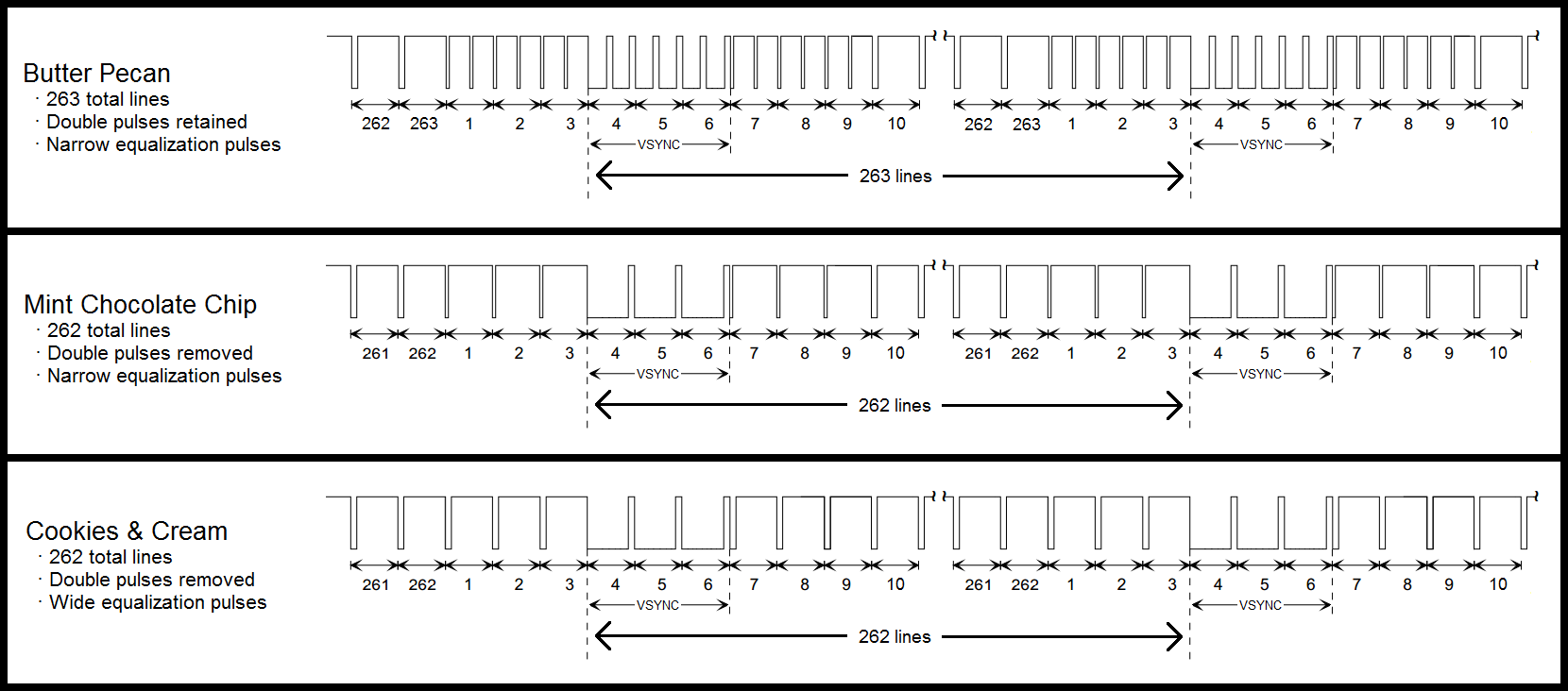
A good opportunity to learn, then! Try to probe what is comming in on pin 32 and on pin 34 of the Denise. Pin 34 should receive a simple 7.14 MHz rectangle signal (_CDAC). Pin 32 would be more complicatec (_CSYNC) and look something like this: https://static1.squarespace.com/static/51f517f0e4b01da70d01ca2a/t/5bd8dfbf1ae6cf1fcecfd38d/1540939711856/240p_flavors.png
from amiga-digital-video.
Bunta714
commented on August 31, 2024
7.09Mhz on pin 34 and pin 32 looks like this:

from amiga-digital-video.
Bunta714
commented on August 31, 2024
A better shot of pin 32

from amiga-digital-video.
c0pperdragon
commented on August 31, 2024
That is very, very interesting. So the _CSYNC signal actually just goes down to about 2.5V for the low pulse. (high pulse is about the correct level of 5V). With this input levels, it is clear why the mod board can not correctly detect the sync pulses.
The question is of course, what causes this stange in-between voltage level. Normally this is a sign that two output drivers try to drive the same line to a different level. Maybe this is caused by your botch wire between Denise and U41. Try to remove this one wire and probe both points independently. My guess is that then pin 9 on U41 will show clean 0V for the low sync level. And Denise pin 32 could actually be pulled to +5V by some yet unknown circuitry. If this is correct, please try to find out what is pulling this pin to +5V. As on the more common variants of Rev.3 (and the schematics in the user manual) this pin is completely unconnected.
from amiga-digital-video.
bkodenkt
commented on August 31, 2024
I have a custom-made adaptor board (mirrored, angled connector to get the case closed) for a CDTV that does work in one CDTV but in the other CDTV machine, it has the same problems as described in the first post: I get a very short Pi0 "rainbow" boot-up screen, then the HDMI loses signal. RGB output is fine all the way, though. Are there any known missing signals on the Denise chip on a rev2.2.1 CDTV board that could cause the same issues you see on a rev3 A500 board?
Am I right that, if I put this board into my rev5 A500, it should work just normally? And, in a swap, the known good board from the A500 should refuse to work in the CDTV as well?
from amiga-digital-video.
c0pperdragon
commented on August 31, 2024
@bkodenkt
I have no special Information on the CDTV beyond what a quick search just gave me. It looks like the _CDAC and CSYNC signals should be delivered to the Denise pins as in the Amiga 500 boards from Rev.5 upwards. So this should actually not be an issue here.
from amiga-digital-video.
Bunta714
commented on August 31, 2024
Here is Denise pin 32 without the wire connecting it to pin 9 of U41.

Here is Hybrid Video IC Pin 18, U41 Pins 9 and 11

from amiga-digital-video.
c0pperdragon
commented on August 31, 2024
That is totally strange! The CSYNC should be a normal signal switching between 5V (approx) and 0V. There must be something preventing it from going down to proper 0V. At least there is nothing funny going on with the Denise input pin itself.
When the schematics is also correct otherwise, the Agnus and the U41 ICs are the only ones connected here. So there must be something strange on either of these two. If you are lucky, only U41 is bad. You could do some more testing on this ICs and probe all its poins (including the power pins) and check what high and low levels you can see on them (should be either near 5V or proper 0V).
from amiga-digital-video.
bkodenkt
commented on August 31, 2024
@bkodenkt
I have no special Information on the CDTV beyond what a quick search just gave me. It looks like the _CDAC and CSYNC signals should be delivered to the Denise pins as in the Amiga 500 boards from Rev.5 upwards. So this should actually not be an issue here.
I just found these schematics, but it is unclear which CDTV board revision it refers to:

CDAC is delivered to Denise, yes, but CSYNC is blank on pin 32, although it had connection drawn to the CSYNC signal that later hits the Video Hybrid. I will keep investigating further. Maybe I can just hook the signal from somewhere else to Denise pin 32.
from amiga-digital-video.
Bunta714
commented on August 31, 2024
It's really odd because the RGB out works perfectly fine via various means (OSSC, RGB CRT monitor, RGB -> VGA cable w/ 15Khz monitor, etc.), and that has a CSYNC signal on it on pin 10, doesn't it? This should be coming from Pin 18 on the Video Hybrid IC?
I am getting some more Pi Zeroes this week, so I will try with a brand new one and see if it has any effect.
That is totally strange! The CSYNC should be a normal signal switching between 5V (approx) and 0V. There must be something preventing it from going down to proper 0V. At least there is nothing funny going on with the Denise input pin itself.
When the schematics is also correct otherwise, the Agnus and the U41 ICs are the only ones connected here. So there must be something strange on either of these two. If you are lucky, only U41 is bad. You could do some more testing on this ICs and probe all its poins (including the power pins) and check what high and low levels you can see on them (should be either near 5V or proper 0V).
from amiga-digital-video.
Bunta714
commented on August 31, 2024
Connected the Denise pin 32 directly to pin 18 of the Video Hybrid IC and it works!
from amiga-digital-video.
c0pperdragon
commented on August 31, 2024
Very good!
So the U41 is somehow able to properly amplify this off-spec signal to send it to the video hybrid.
Still a very strange behaviour, but if it now works for you, that is all that is needed.
You could also have used pin 11 of U41 which is basically the same trace as the video hybrid input.
from amiga-digital-video.
philipkonkyl
commented on August 31, 2024
@Bunta714 or @c0pperdragon. That sounds awesome. could you send be a picture of where I should try to connect it to. Right now I have solder everything on the back of the motherboard ? :-)
from amiga-digital-video.
c0pperdragon
commented on August 31, 2024
@kipper2k This is a very neat solution for the HDTV.
I didn't know that it is quite possible to fit a FFC cable into a socket that has more pins. But probably this is just a matter of holding the tongue at the right angle while fitting the cable ;-)
from amiga-digital-video.
c0pperdragon
commented on August 31, 2024
@philipkonkyl
I marked pin 11 of the U41 chip. This the trace were Bunta714 successfully took the CSYNC signal from. I have no idea if that will also work for you, but you can try. Solder the cable from Denise pin 32 to U41 pin 11 instead.

from amiga-digital-video.
bkodenkt
commented on August 31, 2024
@bkodenkt
I have no special Information on the CDTV beyond what a quick search just gave me. It looks like the _CDAC and CSYNC signals should be delivered to the Denise pins as in the Amiga 500 boards from Rev.5 upwards. So this should actually not be an issue here.I just found these schematics, but it is unclear which CDTV board revision it refers to:
CDAC is delivered to Denise, yes, but CSYNC is blank on pin 32, although it had connection drawn to the CSYNC signal that later hits the Video Hybrid. I will keep investigating further. Maybe I can just hook the signal from somewhere else to Denise pin 32.
Problem solved. It was NOT a missing signal. I accidentally swapped the microSD card with the card in my working rev5 A500 RGB2HDMI and it worked. Turns out that the new microSD I used on the CDTV RGB2HDMI was somewhat faulty. I used another card, same brand and size, and new as well, and that one works. Soooooo, even if a problem looks the same, it can have a totally different reason...
from amiga-digital-video.
 LejonD
commented on August 31, 2024
LejonD
commented on August 31, 2024
For the CDTV i just redone the shape of the a500 version. I done similar to this as to the A600, basically made a signal breakout board for denise and trnsferred them to the 20 pin FFC cable, the cable length is 30cms (1,0mm pitch)
i'll find some pics
The case closes fine. I redone it to fit on the right side plate at the back and made the left plate for joy/serial mouse/usb mouse and a500 keyboard input. ( imade a little error on the back pcb that i had to run a jumper.
Also you can see that i used a 32 pin ffc header as i didnt have a 20 pin one handy at the time but the boards are set up for 20 pin FFC cable. Picture quality is awesome! The final version has only the 20 pin FFC headers on the pcb.
The hdmi connectors from the Pi were bought from https://www.buyapi.ca/search.php?search_query=diy%20hdmi§ion=product
You don't need to buy the cable, any 20pin 0.5mm pitch cable will suffice.
I initially done this design with a 20 pin IDC through hole connectors. I got rid of them as there isn't enough space up top to close the case so only FFC is needed
I like the CDTV version you build, are the PCB layout available so I can duplicate a version for my CDTV.
from amiga-digital-video.
 ChrisFredriksson
commented on August 31, 2024
ChrisFredriksson
commented on August 31, 2024
I'm also wondering if the CDTV version is available somewhere? Would love to get me one of those!
from amiga-digital-video.
bkodenkt
commented on August 31, 2024
I'm also wondering if the CDTV version is available somewhere? Would love to get me one of those!
@solarmon sells some pieces on Amibay and Mateusz K on Facebook in the big Amiga group.
from amiga-digital-video.
ChrisFredriksson
commented on August 31, 2024
Would be great with some links if you know that they are being sold there? I would still love gerbers/KiCAD files/stl files and such if its available so I can make those myself.
from amiga-digital-video.
solarmon
commented on August 31, 2024
I'm also wondering if the CDTV version is available somewhere? Would love to get me one of those!
@solarmon sells some pieces on Amibay and Mateusz K on Facebook in the big Amiga group.
I don't have a specific CDTV version at the moment - but the Denise DIP FFC breakout hat version should obviously technically work, but won't quite be the correct form factor. I see @kipper2k already has a very nice CDTV version as shown above - #28 (comment)
from amiga-digital-video.
ChrisFredriksson
commented on August 31, 2024
I know, but there is no contact information to the mysterious @kipper2k, his website is gone, he almost never replies in threads unless he needs help or has questions. I'm just hoping that he will respond or at least if someone else got the design off @kipper2k to share perhaps..?
from amiga-digital-video.
solarmon
commented on August 31, 2024
I know, but there is no contact information to the mysterious @kipper2k, his website is gone, he almost never replies in threads unless he needs help or has questions. I'm just hoping that he will respond or at least if someone else got the design off @kipper2k to share perhaps..?
See Amibay sales post for another option, but I don't know if there are still any left:
https://www.amibay.com/showthread.php?118447-RGBTOHDMI-Adapter-for-CDTV
I was thinking of doing a CDTV version myself, which would mean the KiCAD design files and gerbers will be freely available. Now that I have a (partially working) CDTV, I should probably do that.
from amiga-digital-video.
ChrisFredriksson
commented on August 31, 2024
Thanks for the link! Those seems to be the "normal" A500 version with an angled header, right? Doesn't seem to hard to modify. But would be awesome to see an expansion variant, like the kipper2k above.
But with all the designs already available, open source, I guess its not too difficult to create that myself either 😀
from amiga-digital-video.
solarmon
commented on August 31, 2024
That version has taken the 'normal' A500 and moved the Pi header the other side, and probably flipped the pinouts so that angled headers could be used.
I'm not aware of that design having the source design files (not gerbers) available.
from amiga-digital-video.
LejonD
commented on August 31, 2024
@kipper2k , doesn't answer much, but i cant use these versions with the Pi on the richt side above the CIA's bacause there is an other project of mine. So i really are intrested in the @kipper2k version
from amiga-digital-video.
 janlugt
commented on August 31, 2024
janlugt
commented on August 31, 2024
I have a rev 3 A500, and the two-wire solution on the bottom of the board offered by kipper2k works like a charm. Tested it before the extra wires were placed, and got a black screen, as expected. Thanks!
from amiga-digital-video.
 MKafke
commented on August 31, 2024
MKafke
commented on August 31, 2024
Hi! I experience the same problem, but with the A500 Rev. 6a mainboard. Perhaps a similar problem?
The rest of my setup is: RasPi Zero W 1.1, RGB2HMDI-Board set to Denise (not SuperDenise).
The RasPi and my Mini-HDMI adapter work. I tried two different monitors and a flatscreen TV.
The monitor says, that an HDMI signal is coming in, but it is just a black picture. The OSD cannot be opened.
I don't even see the Pi splash screen.
from amiga-digital-video.
Related Issues (20)
- Flashing of screen from amiga to black when change ntsc amiga 500 to pal 50hz for games HOT 4
- Colors not right HOT 4
- Amiga 500 Rev 6A Video problem HOT 2
- Not possible to get stable image on A500+. HOT 4
- HDMI vs. DVI HOT 4
- Workbench screen doesn't fit 4K 28'' screen boundaries HOT 1
- Atari ST discussion Part 2 HOT 28
- Amiga pink sparklies on black/grey transition HOT 1
- RPi Zero 2 Support HOT 27
- Pi rainbow splash screen flashes and blank
- Output to TV HOT 2
- New stable RGBtoHDMI software release
- Atari ST Mono LED Flash HOT 3
- Hired Guns - Menu Black Outs HOT 6
- amiga 500 pixelated image HOT 2
- Unable to activate Single Button Mode for OSD menu HOT 3
- Elfmania game - top and bottom of the picture cut off
- A2024 emulation?
- No output when using ribbon cable on Amiga 600 HOT 1
- ECS Support
Recommend Projects
-
 React
React
A declarative, efficient, and flexible JavaScript library for building user interfaces.
-
Vue.js
🖖 Vue.js is a progressive, incrementally-adoptable JavaScript framework for building UI on the web.
-
 Typescript
TypeScript is a superset of JavaScript that compiles to clean JavaScript output.
-
TensorFlow
An Open Source Machine Learning Framework for Everyone
-
Django
The Web framework for perfectionists with deadlines.
-
 Laravel
A PHP framework for web artisans
-
D3
Bring data to life with SVG, Canvas and HTML. 📊📈🎉
-
Recommend Topics
-
javascript
JavaScript (JS) is a lightweight interpreted programming language with first-class functions.
-
web
Some thing interesting about web. New door for the world.
-
server
A server is a program made to process requests and deliver data to clients.
-
Machine learning
Machine learning is a way of modeling and interpreting data that allows a piece of software to respond intelligently.
-
Visualization
Some thing interesting about visualization, use data art
-
Game
Some thing interesting about game, make everyone happy.
Recommend Org
-
Facebook
We are working to build community through open source technology. NB: members must have two-factor auth.
-
Microsoft
Open source projects and samples from Microsoft.
-
Google
Google ❤️ Open Source for everyone.
-
Alibaba
Alibaba Open Source for everyone
-
D3
Data-Driven Documents codes.
-
Tencent
China tencent open source team.
from amiga-digital-video.