c0pperdragon / amiga-digital-video Goto Github PK
View Code? Open in Web Editor NEWAdd a digital video port to vintage Amiga machines
Add a digital video port to vintage Amiga machines


I got a request about the possibility to turn off the HDMI output in certain circumstances. The main use would be to allow switching between the HDMI output of a Vampire card and the RGBtoHDMI automatically. But it could also be useful for implementing a simple video power-down mode.
@ian
I could imagine that the Amiga can be be programmed to turn off/suppress its csync signal (will check this). What would happen then on the side of the RGBtoHDMI? Would it just continue to display the content of its framebuffer, or would it turn off the output alltogether? Could such a behaviour be implemented?
There have been quite a few questions about the lag of the RGBtoHDMI software. The theoretical lag is around 3.4 milliseconds which is the software timing difference between the computer's vertical sync pulse and the HDMI output's vertical sync pulse. It used to be a little lower but I had to increase it by around 1 millisecond to avoid tears when using the aspect ratio conversion and some other settings.
I also measured it using an oscilloscope as follows:
I connected a HDMI to VGA converter to the output of the Pi to give an analog output and then displayed flashing white frames on the source computer, one frame of white followed by 7 frames of black (the VGA converter I was using had minimal lag). I then connected the computer's green output and the VGA converter's green output to the oscilloscope with the following results:
This shows 4 flash frames. Yellow is the source computer and cyan is the output of the Pi zero via the VGA converter.

Looking at this in closeup shows a difference of 3.6 milliseconds which is very close to the theoretical value above. The additional lag is likely due to the integer scaling in the Pi's scaler and the VGA converter.

The lag will vary by a small amount depending on the source computer's refresh rate and the scaling settings (maybe plus or minus half a millisecond). It will also increase significantly when the menus are on screen because normally the data is sent so fast to the HDMI port there isn't enough time to draw a menu over it so to get the text on screen a delay has to be introduced to allow time to actually draw the text on top of the video although that doesn't really matter as you won't be playing games with the menus on screen.
In his review, Jan Beta had a problem with his HDMI capture card.
The most likely cause of this is that the Pi zero is configured by default to output a DVI compatible RGB HDMI signal so that it can work with older 4:3 DVI monitors as well as more recent 16:9 HDMI monitors.
This can be changed by editing the config.txt and default_config.txt files.
Load both files into a text editor and change the following line from:
hdmi_drive=1
to
hdmi_drive=2
Then save the files back to the SD card, reinsert into the Pi zero and reboot.
(Both files have to be edited because the config.txt file is occasionally re-created from the default_config.txt file when certain settings are changed)
(Changing to hdmi_drive=2 will stop the output working with DVI monitors)
If that doesn't work there are other hdmi settings that can be changed in the config file detailed here:
https://www.raspberrypi.org/documentation/configuration/config-txt/video.md
The one most likely to change things is hdmi_pixel_encoding:
0 | default (RGB limited for CEA, RGB full for DMT)
1 | RGB limited (16-235)
2 | RGB full (0-255)
3 | YCbCr limited (16-235)
4 | YCbCr full (0-255)
So try adding the following line just below the "hdmi_drive=" line
hdmi_pixel_encoding=3
or
hdmi_pixel_encoding=4
If someone with the problem can confirm that changing anything from the above fixes the issue I'll add a menu option to switch between the various modes to save having to edit the text files.
Would it even be technically possible to bring some "new" cool graphics modes, compatible with either Grafitti or ColorMaster 24 (or 12) to the RGB2HDMI?
Just tossing some ideas... :)
Does the arduino testpattern.ino sketch still work with the latest released (as of a few days ago) version of RGBtoHDMI?
I'm running it on a regular(328p) arduino mini-pro (it's what I had available). That's not different enough to cause problems with the sketch working is it? I had to remove the power_usb_disable(); call as it doesn't have internal USB and also comment out TIMSK3 = 0x00; and TIMSK4 = 0x00; as those interrupts aren't present, but apart from that, the 328p should behave otherwise identically to a 32u... no?
only i'm not getting any activity from my Pi on my test rig. (well apart from boot colour splash)
I've verified the logic gates are operating correctly with an extended blink sketch, when CDAC is pulsed, it clocks the changes through the flip-flops and I see the outputs toggling. I have also verified that piclk signal is changing at the pi (with a meter, not a scope unfortunately) but no activity when a Pi is attached. I've tried a TV, a monitor and a HDMI capture dongle.
This is a non-destructive way of fitting an HDMI output to the Amiga 500.
When adding the RGBtoHDMI adapter to the original Amiga 500, the problem arises how to get the HDMI cable out of the Amiga.
I've come up with the following solution:

This little housing, for a Female HDMI connector, clips right on the Amiga case. I tried to design it in the A520 TV modulator style, so it should not look too much out of place in the 80' computer design.

The cables go through the small vents on top of the Amiga case.
I've made a complete guide on prusaprinters.org, where you can download the STL files and see how to assemble it.
https://www.prusaprinters.org/prints/63688-rgbtohdmi-adapter-housing-for-amiga-500
Hope someone finds it usefull.
I have set up this thread as a forum to discuss the options with @IanSB concerning the use for the RGBtoHDMI project.
Hi
I've been having quite a few failures building these RGBtoHDMI v2 boards. One of the issues I'm finding is that the solder mask clearance does not have enough tolerance and there could be manufacturing variances, and bad soldering techniques, that could lead to exposed copper and shorts occurring.
The issues seems to be that the copper pour clearance is set the same as the solder mask clearance - both at 0.2:


In the 3D viewer you can see that there is potential for copper to be exposed, depending on the manufacturing process tolerances.

So you could end up getting solder shorting on to the copper pour - here are a few of my examples of pins shorting to the +5V copper pour:


To get around this issue, I would normally set the copper clearance value to something slightly bigger - like 0.254 - so that the solder mask will always be covering the copper pour edges.
Continuation of #4
After collecting more data and the reports from @andriodious, everything started to make less and less sense.
So I started to doubt my assumption about the meaning of the +ve and -ve options in the sample menu. I always thought that +ve would mean the rising edge of the pixel clock and -ve is the falling edge. As it turns out, this it is just the other way round. So I managed to provoke image jitter with one option I previously considered safe: Trailing -ve
So everything I said in the previous post is exactly the same, but with "+ve" and "-ve" reversed.
Considering the matter, using +ve (which is in fact the "safe" option) should cause Denise and SuperDenise to have the same pixel alignment. This is my profile which fits perfectly on my 1280x1024 screen:
Amiga_LeadingEdge_+ve.txt
Could you give this profile a try when you continue with your Amiga 500+ ?
I can't seem to find the BOM for the Denise adapter board. I downloaded the gerbers, and had a set of boards made at OSHPark. Got a BOM file for those of us soldering the thing together ourselves? Maybe I'm missing it.
!!Oops: Wrong title: I meant 10 boards.
I spent parts of yesterday and today to assemble 10 Revison 2 adapters (feeling like a christmas elf all the while ;-) ) .
As it turns out, this is really labour-intensive so I need to adjust my prizing a bit (also to cover various overhead losses).
I can give out these adapters now for €29 plus shipping (€6 in Austria, €10 in Europe, €15 international, UK is currently not possible due to canceled air traffic).
Payment only via paypal to my account: [email protected]
Please reserve your adapter(s) by email and wait for my response before transfering any money.
If you cannot get any of these right now, do not worry. I will continue to make the adapters as long as there is demand.
I created this thread as a means to collect feedback about your experiences using this solution. Installation pictures and screenshots are highly welcome.
Continuation of #3
@IanSB
Would it be possible to provide a specialized settings menu that can be controlled with a single button? Like press to switch through options and press long to select.
For the internal installation in an Amiga 500 I would like to place the HDMI port at the small unused area on the backside and put the single push button next to it.
Its main purpose would just be to select different output resolutions and maybe the framerate.
Continuation of #1
Hi!
The first thing is thanking you and everybody that worked on this marvelous little board granting our Amigas with the power of HDMI output! Many, many thanks!
As to the subject of this issue, in your wiki you mention the possibility of using an audio injector as to inject the analog audio signal of the Amiga in the HDMI signal. Liking the idea I bought the exact model of audio injector you link in the wiki, but I'm having problems in connecting it with the RGBtoHDMI output.
What's happening is that it seems that something in the signal produced by the RGBtoHDMI prevents the injector from doing its job: if I connect ONLY audio, I can hear the Amiga audio on the HDMI, if I connect another HDMI source (I've tried with my RPi4, for example) I can see the RPi4 video AND hear the Amiga audio, but if the Amiga RGBtoHDMI out is connected... then I only see the Amiga, but no audio!
Any advice on what should I try changing in the settings as to get it work properly?
Any indications of what do the various HDMI mode settings mean? It seems that my 4k display doesn't like any of them besides DVI compatible... What am I doing wrong?
And what CPLD do I have in my board? Would it be useful using the CPLD menu to reprogram it?
Thanks again for your hard work and for any advice you might have!
Seems there's a bit of a shortage of TLV74333PDBVR.
Most suppliers seem to have none and are quoting 16 weeks lead time.
The few that have them are quoting daft postage and packaging unless I buy a 1000 or more.
Are there any alternatives ?
Just installed everything today and I am very impressed.
However sometimes on start up, the image will be shown in a red hue. Other times the colors will be correct but some pixels will be flickering side to side (mostly in the middle of the screen). And other times the picture is perfect.
Any idea how to remedy the two problems?
Hi,
I'm testing out several Pi Zero relocation adapters - there are three types: A, B and C:
Type A is just flips it over:

Type B shifts it sideways and flips it:

Type C shifts it sideways, flips it and rotate it:

Type A works fine without any issues.
However, type B and C has video artefacts where on certain edges there are pixel 'sparkles' artefacts.
I'm aware that this is due to the increased signal traces, but is there anything that could be done to improve it?
Thank you.
So would something like this : https://www.robotshop.com/en/io-hat-raspberry-pi-zero.html
help with the need for additional pins to handle more bitplanes? (IE A1200/A4000) ?
I was thinking about to the possibility to create an internal modification for the Amiga using your RGBtoHDMI software.
As you have stated, it is possible to pump enough data into the Pi to allow the EGA+ mode with 6bit per pixel. The Amiga (original screen modes only) has basically the same data rate. Twice the bits per pixel, but with half the pixel clock (about 14..2 MHz). So I assume this should be possible with the current system and without resorting to DMA.
The beauty of this mod lies in the fact that the only non-standard part necessary is a simple adapter board that level-shifts the output signals of the graphics chip to 3.3V and exposes them via a 2x20 pin socket (very much like my C64 adapter board). The RPi Zero can then directly be plugged into this socket to sit above the graphics chips. The HDMI output then needs to be transfered somehow outside of the case (probably with a mini-HDMI to HDMI extender cord).
This would be such a cost effective solution to upgrade the Amiga to perfect HDMI (without sound though), that I could imagine quite some people will want such a solution.
One small unsolved issue remains, though. The system clock is only 7.1 MHz, and the graphics chips changes the output signals on both edges of this clock (very much like the atari 8-bit machines).
Would this be manageable by the RPi software, or is some additional circuitry necessary? I can imagine to add a latch to keep 12 pixels of one half of the clock and then provide 24 pixels together at half the pixel rate. But only if it can not be solved in software already.
If you think this is possible, I will try to create a device profile - but I will surely need some help for this.
Is the new ECS mode support working for the A3000?
There is a new software build available here:
https://github.com/hoglet67/RGBtoHDMI/releases
This is one step above the previous betas and is a release candidate for the next stable version
This version has the following improvements over the version previously available on the above link:
Support for NTSC machines.
Aspect ratio conversion to make NTSC games full screen on PAL machines
Fully variable scanline level
Support for flash floppy OSD
Much faster 12 bit per pixel capture code
Various bug fixes.
To use scanlines, there are three profiles to choose from:
Amiga
Amiga Blk-scanlines (Black scanlines only)
Amiga Var-scanlines (Variable scanlines)
Note the variable scanlines profile is more CPU intensive and has to overclock the CPU so if you have problems revert to normal Amiga or black scanlines only or fit a heatsink on your Pi zero.
For flash floppy OSD:
Connect the Flash floppy video signal to PIN 18 on the Pi zero header via a 1K resistor
(Video must be 3.3v logic level)
Note PIN 18 was an output on earlier software so you must use a resistor to protect the FF OSD pin in case older software is loaded.
Please post any issues you find when using it with the Amiga board here.
Sorry, don't know the best place to ask questions like this.
How dependent is your daughterboard on receiving the signals from denise pins directly? Could this potentially be made to work by taking output from the RGB out on the back and feeding that into your pcb to pass to the pi creating an external upscaling solution that should work with all denise chips/a1200/etc etc anything with an rgb out? Or is it that by the time it gets to the output port the signal is analog and no good for what you're doing?
Hi @IanSB
As previously mentioned: When using 1280x1024 output resolution, an interlaced workbench is off by one interlaced line.

This can also not be fixed by adjusting the vertical offset, because then the picture is too up.
Even if it could be fixed by adjustements, I guess, the non-interlaced picture would be off instead.
For larger output resolutions this effect is basically the same, but there it is not so noticable:


Created a new specific thread. The previous was getting too long already.
My profile is now this:
Atari_800_14Mhz.txt
As I have seen as comments in my palette generation program, I unsuccessfully tried to create a palette from an algorithm. This just did not look good, so I have switched over to a pre-made one.
But it also had color issues as well
I have now downloaded a bunch of different variants and will try which one maches my TV best.
by the way: I just spotted a glitch in my firmware. So far it appears in only one demo that messes with sprites...
Hi there!
I have this very strange video issue. Picture looks crisp clear, but with three ribbons of weirdly (wedge-)shaped garble horizontally..
When first turned on, they move a (very) little bit vertically, but after that, they stay where they are on the photo.
Any spontaneous ideas?

B.t.w. This is running on a Rev5 A500, with kickrom-adapter and kickstart 1.3 on EPROM. Analog video output looks amazing. This board was bought from and built by a 3rd party. I soldered the headers to the pi and went through them again this morning the solder joints there look fine, added a bit of solder to a couple of them where i may have been a bit quick last night. Anyway. Same issue still. There are no other interesting wires needed for Rev5-boards that i have may have missed?
I am creating a new thread specific for Atari ST discussions.
I don't have a (nor ever had) and ST myself, so my experience is pretty limited.
But I would guess that your auto-detecing solution could be the most general solution and allows
a no-hassle access to both games and professional (music?) applications.
Documentation for the video hardware is a bit hard to find, but if the Shifter is indeed a 40pin DIP, a similar solution to my Amiga board should be possible. No idea of the clearance of course and of possible case variants.
Guessing from some pictures it seems that there is an optional RF modulator next to the metal can in which the shifter sits. Removing this RF modulator (when actually installed) gives plenty of space to put the RPi just in the right spot to make the HDMI output accessible from the outside.
From an adapter board with the same height profile as for the C64 and Atari 8-bit (40-pin DIP socket with long solder tails), a short 40-pin ribbon cable could go the RPi, through a slit cut in the RF shielding.
When the Shifter has an additional 5mm clearance before reaching the metal shield, this should work.
I set up this thread to keep anyone informed who wants to buy an assembled adapter from me.
My first builds are nearly sold out (all ECS are gone or reserved) and I am in the process of ordering more parts. I will keep you informed.
Hi there,
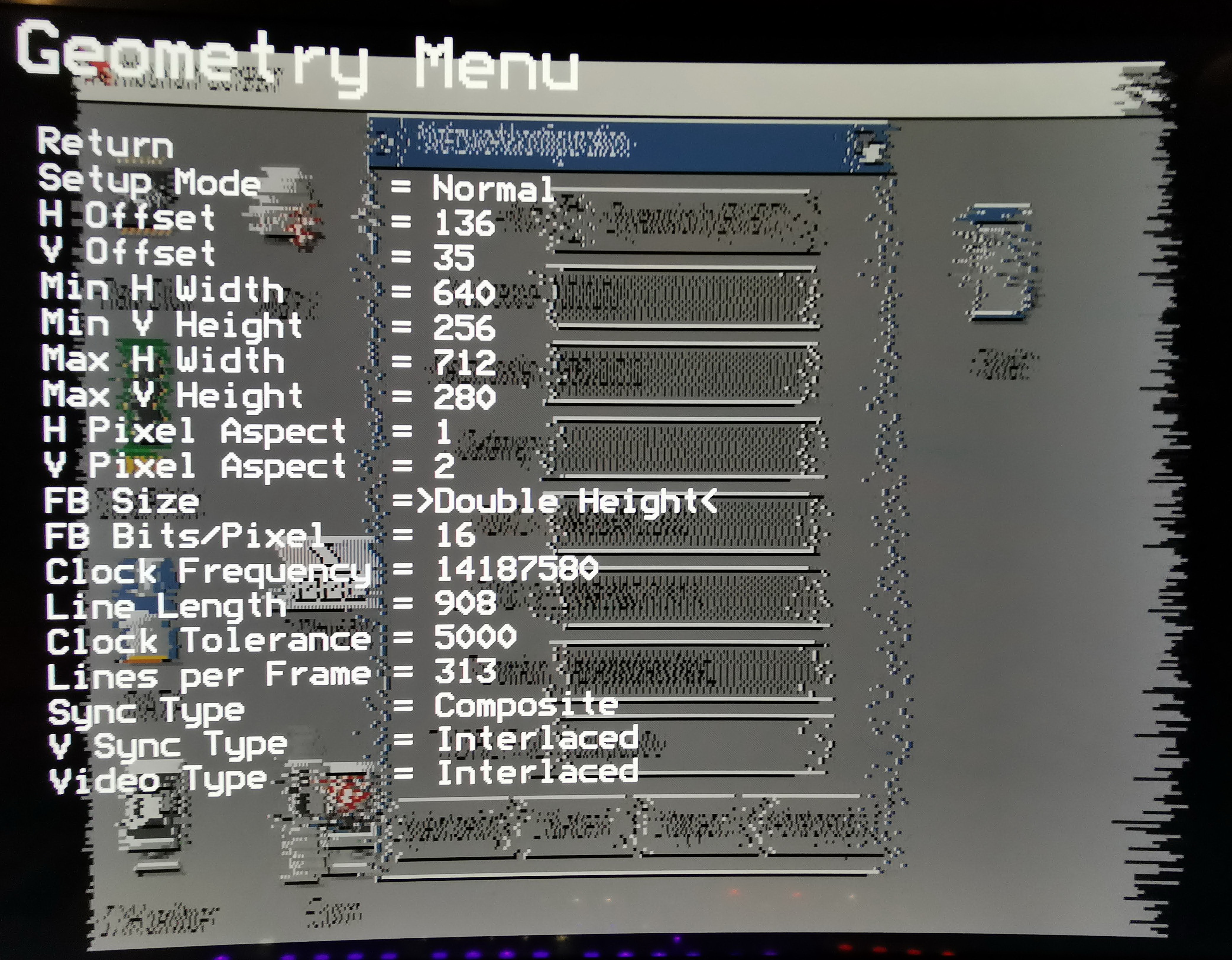
I use the adapter in my Amiga 500 and am very enthusiastic about it.
I only have one problem with the scanline option.
I activated it in the Preferences menu and then changed the "FB Size" from normal to double height in the Geometry menu.
Before, I had a sensational picture (ignoring the distortions from the cell phone camera)
But after the change, I have a totally shaky picture.
The photo is only a snapshot, in real life it is constantly shaking.
Am I doing something wrong or is it a general problem?
Maybee @IanSB knows about this?


First, thank you for this cool project, and all the effort you put into, but please consider to reopen issue #20 (Audio IN to HDMI).
Yes, I know the code is bare metal and already tight, but probably there is just enough time to read some samples from an i2c connected ADC in the horizontal and vertical blanking intervals and insert them in the HDMI stream. Audio quality should not be such an big issue, because the sample rate has only to be slightly higher than double the output rate of Paula (see Nyquist–Shannon sampling theorem) to get decent quality.
Relaying on an external solution (HDMI audio inserter) is both inelegant and cumbersome, when the Raspberry Pi could just insert the audio itself in the first place.
Is there a setting in the menu that is known to fix flashing of screen on amiga 500 when i put my ntsc amiga 500 in 50 hz pal mode. I didnt want to mess with the settings too much until i asked if this is a known issue with a solution. I will continue to trouble shoot on my side, but any help would be appreciated. its just a stock 500 rev 6 mb 1 meg ram, fat agnus so does pal, but only have 2.10 kickstart. i was able to rekick into 1.3 but same issue when used degrader to change to pal 50 hz.
Hi!
I can not help but keep obsessing with the idea of a general upscaler based on the Raspberry Pi Zero (1.3 or older). As it looks, the video camera interface is very non-disclosed, so the best chance is still the GPIO header.
Leaving performance issues inside the Pi aside (could possible be solved by using DMA), the header pins seem to be just enough to pull this off. In a bare-metal implementation, the ID_SD and ID_CL pins can be used to directly control the TVP7002, as it conveniently has a I2C control interface. With 24 pins for color, 1 for pixel clock, there is exactly one GPIO pin left to transfer the sync. The video chip generates hsync and vsync, but these could be XORed to form a poor-man's csync signal.
The chip has multiple video input lines, so the device could easily have ports for YPbPr as well as SCART (the first with either YPbPr or RGsB, the second with RGBS or RGsB).
Some control buttons can be done with an I/O-expander on the I2C bus to switch input source, output resolutions and to tweak the input sampling.
Going completely crazy, I could even imagine to integrate a solution to digitize stereo audio as well and make the data accessible through the I2C bus. With 1.7 MHz bus speed, this may just be fast enough to transfer 44kHz 16bit stereo audio.
All this of course implies that the Raspberry Pi Zero has the dedicated hardware to run the GPIO input as well as the I2C communication independently of the CPU.
Even if audio is not possible, it would be an awesome device.
Hello.
Are all RaspberryPi Zero Pins already in Use?
If not, could two Pin´s be used to get, the Audio-Analog-Signal into the HDMI signal?
If not Analog? then maybe the DAC out pins for Left and Right?
And of course if no Pins are free on the RPi maybe an Interrupt-based Audio signal "insertion" on the next iteration of the PCB?
I am very Far away of Electronics-Engineering but maybe it is a tiny suggestion.
c.u. Zui from Hamburg Germany.
Hi all,
Have tested this with 2 different Amiga 500 Rev3s and neither will work with the adapter. The Pi splash screen will appear but the Rev3 refuses to display (black screen only) through HDMI. I have swapped Denise and the Agnus with no joy. I can't find a schematic on the Rev3 for comparison so not sure what the issue is.
It might be possible to implement support for other relatively simple systems, maybe with a buffer board and just Pi software or possibly using the 14 bits available on CPLD with the new 12 bit board in a similar way to the proposed direct 48K Spectrum connection.
A few machines that this might work with:
Atari 2600
VIC 20
Commodore 16 / +4 (TED chip)
Hi, hopefully this post is in the correct place. Do you have a BOM publically available for this as i would like to build myself a couple of these. I seen the V1 pdf but not the V2 version.
Thanks
I've built several of these boards for friends and have been using 3 different IC for U1/U5:
The ones using the Nexperia ICs after a while fail with random bursts of this pattern for a second or two when in Super Denise mode:

I can think of two possible reasons for this:
It could even be a combination of both, the floating input causes a high power draw which is causing too much load for the regulator.
I have a reworked design for the PCB I'll test in a few months time which:
I'd also probably recommend using at least a 400mA regulator.
If anyone wants to test this before I get a chance, the work in progress is here (I haven't updated the Gerbers there yet): https://github.com/LinuxJedi/RGBtoHDMI/tree/amiga-slot-fixes
Hi,
I have this internal gotek and OSD does not work, over RGB cable it is ok.
https://www.sellmyretro.com/offer/details/amigotek-ff-osd-39893?fbclid=IwAR098xZAcUs8Bv4w7vhVoUmL9JhAcdb9fq1oAJ8F7dV_NatcxiR9coH03Yc
Any solution maybe?
Hi,
I build two A2000 slot rgb to hdmi adapters, and on both I have a problem with sparklings on edge of icons.
Look at the video with problem:
https://youtu.be/2YZ0NK6CTBE

What I miss on this boards?
I build classic RGB to HDMI adapters V1 and V2, and never get any problem.
Thank you!
Would be nice to add http://wiki.icomp.de/wiki/Graffiti emulation.
This thread is intended for discussions on how to get machines working with the generic small adapter board.
I don't intend to actually build such boards, as it should be fairly easy for anyone experienced enough to also do the rest of the installation.
I encourage the use of this thread as a means of communication to help each other with difficult installs and maybe to source parts or PCBs in a more cost-effective way.
Specifically for the A600, user @culexus8 made a very clear diagram on where the connect the various wires. This seems to be working quite nicely:

Can you check out the latest version of RGBtoHDMI with the Amiga board to see that it still works OK. I've changed the menus so they don't flicker in interlaced mode by switching to progressive capture when the menus are on screen (The image under the menus will be at half vertical resolution).
The wiki has been updated to cover recent changes:
https://github.com/hoglet67/RGBtoHDMI/wiki/Quick-Start-Guide
https://github.com/hoglet67/RGBtoHDMI/wiki/Reference-Guide
Can anyone tell me if scanline level option in the OSD works? I can't seem to change the value from 0?
Enabling scanlines work, but not scanline level?
Thanks
Thanks very much for all the hard work on this project! I got some V2 PCBs printed and I assembled one today, but I'm just getting a black screen on HDMI and I'm wondering if somebody can help me troubleshoot it.
Some notes:
Can anyone think of anything else I might test to troubleshoot this? I don't know much about diagnosing stuff with the scope, especially when it comes to video signals, so I'm not sure if any of the above is valuable information. Is there any config option tweaking I can do on the Pi side to output a test signal?
(One more thing: just ONCE I saw the multicoloured test screen when the Pi with RGBtoHDMI started, but I think it was after switching from the Rasbian to the RGBtoHDMI microSD so perhaps there was some kind of bootloader cache thing going on)
Thanks in advance!
As I understand it, part of the problem for ECS and AGA machines is the processing power of the PiZero. I was wondering if @ianb might know if the processing power of the Pi CM4 or even a Pi4b attached to a card in a BigBox video slot might do the trick for the A2000s, A3000s and A4000 variants. The question came about after a discussion with Reinhard Grafl in which he mentioned
OK, I get it. Looking at the schematics of the A2000 and A3000, the video slots provide all necessary signals from the (Super)Denise and power as well, so it would actually be possible to design an adapter
that fits in there and that can also carry the Raspberry Pi. Maybe someone actually wants to make such a board.
For the A4000, the Lisa chip still can create much too much video data do be processed by the Pi. Restricting this to OCS screen modes would be a very unsatisfying solution.
Given this, and given the Pi CM4 (Compute Module 4) and Pi4B have more the double the resources of the PiZero, I was curious if this might be a future path. Also, given the CM4's size, it might be a more viable option for the A500s and A1000s of the world.
The Denise adapter would fit nicely in an A1000, but there's no chance to fit a Raspberry Pi Zero there, since Denise is just next to the PSU. Would it be likely to work if I connect the Pi using a ribbon cable, and place it somewhere else, or would that introduce noise that would ruin the quality?
I'd need to do some motherboard mods for this to create the /CDAC signal and bring that and /CSY to the Denise socket, build a new adapter with a pin header for the Pi, as well as making a suitable ribbon cable, so I prefer to check first whether it's worth it.
Hi,
I just built my first RGBtoHDMI v2 board but having some trouble with the pin header strip alignment to the Denise socket on the motherboard (of an rev 8A A500plus).
Using a bare board you can see how the holes line up with the Denise socket holes.

I'm using the pin headers from:
Which are different from the longer and thinner ones like at:
When I use the pin headers from LCSC, they do not seem to be line up with the Denise socket holes and I cannot get it to fit in to the socket:

Can somebody offer some advice on what header pins should be used and if there is any special build instructions for them.
Thank you.
I've searched the code for references to GPIO pin 18, and as far as I can see it's never set as an input pin. It's used to signal something to the adapter card. So why is R1 there on the Denise adapter? All it does is to pull this output pin to ground, right?
I have by mistake used a far too small resistor, so I'm wondering if I can simply remove it.
A declarative, efficient, and flexible JavaScript library for building user interfaces.
🖖 Vue.js is a progressive, incrementally-adoptable JavaScript framework for building UI on the web.
TypeScript is a superset of JavaScript that compiles to clean JavaScript output.
An Open Source Machine Learning Framework for Everyone
The Web framework for perfectionists with deadlines.
A PHP framework for web artisans
Bring data to life with SVG, Canvas and HTML. 📊📈🎉
JavaScript (JS) is a lightweight interpreted programming language with first-class functions.
Some thing interesting about web. New door for the world.
A server is a program made to process requests and deliver data to clients.
Machine learning is a way of modeling and interpreting data that allows a piece of software to respond intelligently.
Some thing interesting about visualization, use data art
Some thing interesting about game, make everyone happy.
We are working to build community through open source technology. NB: members must have two-factor auth.
Open source projects and samples from Microsoft.
Google ❤️ Open Source for everyone.
Alibaba Open Source for everyone
Data-Driven Documents codes.
China tencent open source team.