Giter Site home page Giter Site logo

dbuezas / lgt8fx Goto Github PK

View Code? Open in Web Editor NEW
349.0 38.0 88.0 54.26 MB

Board Package for Logic Green LGT8F328P LGT8F328D and LGT8F88D

Makefile 6.28% C 51.88% Shell 0.23% C++ 29.36% Assembly 9.95% Processing 0.30% PHP 1.85% JavaScript 0.15%
arduino lgt8f328 core boards clock-speed differential amplifier board manager chinese

lgt8fx's Introduction

How to install

Add the package to the arduino Boards Manager Urls:

  • Go to Preferences
    • paste this url in Boards Manager URL: https://raw.githubusercontent.com/dbuezas/lgt8fx/master/package_lgt8fx_index.json
  • Go to Tools/Board/Boards manager
    • Type lgt8fx in the search box
    • install lgt8fx

Now the boards appear in the IDE. You can also select clock speeds, upload speeds and generic boards with external cystal.

Boards Manager

Variants

Clock

External Clock

32Mhz is twice as fast as a conventional arduino nano! Actually even faster as many operations take less clock cycles than in the atmega328p. Check out some benchmarks

Recommended read

Tutorials and details about this board: LGT8F328P - LQFP32 Boards • Wolles Elektronikkiste

Discussions, ideas, questions and show your project

Features

Timers

This chip has more timers, each with more features than the atmega328p. Explore, configure and visualize timers for both atmega328p and lgt328p with this online tool https://github.com/dbuezas/arduino-web-timers image

Differences to original core Larduino_HSP v3.6c

  • Support 32 Mhz and other clock speeds
  • Selectable ADC resolution (Arduino compatibile default is 10 bits)
  • Differential Amplifier API
  • Better Boards Menu
  • Installation via Board Manager Urls
  • SoftwareSerial @32Mhz
  • FastIO ported from https://github.com/LGTMCU/Larduino_HSP

Power consumption @ 5v

Clock Pro mini style w/o power LED Pro mini style Nano style
32MHz 12.7mA 15.0mA 32.6mA
16MHz 9.2mA 11.5mA 27.8mA
8MHz 7.1mA 9.4mA 25.4mA
4MHz 5.9mA 8.2mA 23.3mA
2MHz 5.3mA 7.6mA 23.4mA
1MHz 5.0mA 7.3mA 22.8mA

Example boards:

-->LGT8F328P-SSOP20

Pro Mini ssop20 Pro Mini ssop20 Pro Mini ssop20

Nano style

Pinout by [wollewald](https://github.com/wollewald)

-->LGT8F328P-LQFP32

Wavgat Pro Mini pseudo-clone Wavgat Pro Mini pseudo-clone 
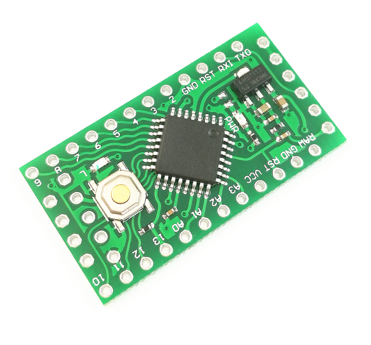
Chip marked as AVGA328P

Pro Mini style

Pro Mini style

Nano style

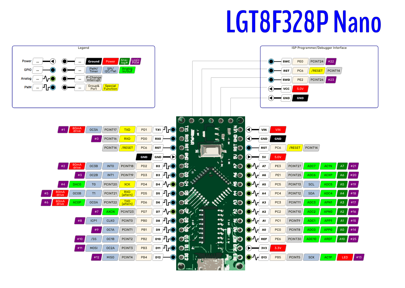
Pinout by wollewald Visit his Electronic projects blog here https://wolles-elektronikkiste.de/en/

Nano style Nano style

Nano style

Nano style

Pinout by wollewald

Like this pinout?

Create more pinouts for the other boards!

Wemos Nano style Wemos Nano style

Wemos Nano style

Uno Style

Uno style

-->LGT8F328D-LQFP32

LARDUINO Uno style

Larduino Uno style Larduino Uno style

-->LGT8F328P-LQFP48

Nano Style

Nano style

Nano style

Pinout by [wollewald](https://github.com/wollewald)

Uno Style

Uno style

Docs & links

PS: Just want to say thanks for this git, helped me a lot!

Disclamer

I have no association with Arduino, Logic Green, Atmel or anything. I just wanted to have a convenient way to use these boards and get them to work without hacks at max speed

Automated Releases

Each time a PR is merged, the release action will be triggered.

The following steps are executed

  • Generate the release artefacts (the lgt8f-1.0.x.zip file)
  • Update the package_lgt8fx_index.json file with the new version
  • Commit and push those changes to the repository
  • Generate a release with the artefact.

PRs that only touch the readme.md file, or the /docs folder will NOT trigger a release.

The action can be found here: https://github.com/dbuezas/lgt8fx/blob/master/.github/workflows/release.yml

Download stats

https://tooomm.github.io/github-release-stats/?username=dbuezas&repository=lgt8fx

Thanks

  • #Larduino_HSP for doing 90% of the work
  • #RalphBacon introducing most of us to the board
  • #dcfusor for help with fast io backporting
  • #HI-SEBA for help with software serial
  • #dwillmore for creating the wiki, serial adapter troubleshooting, more examples of boards and wemos-TTGO-XI board support
  • #seisfeld for adding in-menu support for an external oscillator
  • #jg1uaa for the updated Software Serial without timing tables and missing methods
  • #LaZsolt for adding SSOP20 lgt8f328p support and accurate delayMicroseconds
  • #jayzakk for fixing the ADC prescaler for faster analog reads
  • #wollewald for all the pinout diagrms

"Buy Me A Coffee"

lgt8fx's People

Contributors

asilichenko avatar dbuezas avatar dwillmore avatar eimiz avatar github-actions[bot] avatar gpb01 avatar jayzakk avatar jg1uaa avatar koolru avatar lazsolt avatar seisfeld avatar superusernameman avatar thinhx2 avatar wollewald avatar

Stargazers

 avatar  avatar  avatar  avatar  avatar  avatar  avatar  avatar  avatar  avatar  avatar  avatar  avatar  avatar  avatar  avatar  avatar  avatar  avatar  avatar  avatar  avatar  avatar  avatar  avatar  avatar  avatar  avatar  avatar  avatar  avatar  avatar  avatar  avatar  avatar  avatar  avatar  avatar  avatar  avatar  avatar  avatar  avatar  avatar  avatar  avatar  avatar  avatar  avatar  avatar  avatar  avatar  avatar  avatar  avatar  avatar  avatar  avatar  avatar  avatar  avatar  avatar  avatar  avatar  avatar  avatar  avatar  avatar  avatar  avatar  avatar  avatar  avatar  avatar  avatar  avatar  avatar  avatar  avatar  avatar  avatar  avatar  avatar  avatar  avatar  avatar  avatar  avatar  avatar  avatar  avatar  avatar  avatar  avatar  avatar  avatar  avatar  avatar  avatar  avatar

Watchers

 avatar  avatar  avatar  avatar  avatar  avatar  avatar  avatar  avatar  avatar  avatar  avatar  avatar  avatar  avatar  avatar  avatar  avatar  avatar  avatar  avatar  avatar  avatar  avatar  avatar  avatar  avatar  avatar  avatar  avatar  avatar  avatar  avatar  avatar  avatar  avatar  avatar  avatar

lgt8fx's Issues

Use picoboot instead of optiboot

I'm not sure how small optiboot compiles down to, but picoboot gets under 256 bytes. Would it be useful to move to it? Since we have our own boards.txt anyway, we avoid the problems of the Atmel chips needing their boards.txt file manually edited.

The only concern would be that boards probably come with optiboot and this would require all boards to be reflashed to picoboot. That's probably a non-starter.

But I though I'd bring it up.

PlatformIO support?

Hi dbuezas - great work on integrating all the parts of this chip for the Arduino IDE - it works perfectly!
As I am doing most of my projects in PlatformIO my question is whether it is possible to port the board definitions over?

Maybe someone else has experience and could chime in how much work this requires.

Thanks again. Best, Arne.

Support for high current pin configuration

According to the datasheet (page 81 in v1.0.5) some pins can be set to a a high current push-pull configuration, allowing for 80mA, instead of the standard 12/30mA. This can be done by setting a register. Any plans to add support for that? It would be useful for stuff like driving mosfets.

SoftwareSerial conflict with other lib that disables interrupts

Hi,

the new implementation of the SoftwareSerial library introduced by @jg1uaa in v1.0.6 via #26 seems not reliable. I updated my core this morning and ran our application with it. We use this library to talk to an MP3 decoder chip at 9600bps using SoftwareSerial. We run the LGT at 16 MHz using an external clock. The mentioned library and the chip uses checksumming to make sure the communication is reliable. With v1.0.6 of the core we get packet header and packet checksum errors which we don't get with v1.0.5.

Wrong pinout picture?

Hi.
I was wondering if maybe the picture with the pinout might be wrong?

If I read it correctly it seems to tell me that pin d2 has pwm. But after stumbling arround for a while this afternoon it seems it is not a pwm pin.
My cheap dso150 scope just shows a flat line and when flipping it with digitalWrite I see pwm blocks.
Checking an nano pinout it does not have pwm on D2.

So is the diagram flawed? Or does the board have pwm on D2 but do I need to do some trick to get it to work?

I am talking about this picture: https://raw.githubusercontent.com/dbuezas/lgt8fx/master/docs/boards/pinouts/svg/LGT8F328P-nano.png

Larger code size in LGT

The compiler produces quite a lot larger code sizes (additionally to having 1k less usable flash due to eeprom emulation), which makes larger Atmega projects impossible to run on LGT.

Blink example:
Atmega Nano: 932 bytes (of 30720)
LGT8F328P Nano: 1060 bytes (of 29696)
=> + 13.7%

Some of my complex code (OLED@I2C, Ethernet@SPI, 4 Keys, 4 channels of FastLED, EEPROM, ...):
Atmega Nano: 30718 bytes (2 bytes left ^^)
LGT8F328P Nano: 32960 bytes (absolutely impossible anymore)
=> +7.2%

Any ideas? ;)

Thank you

Bootloader upload and freeRTOS

Hi - thanks for all of your work... I have several LGT8fs and love them..... except...

2 issues when using your package....

#1 - I cant load the bootloader...
Arduino: 1.8.10 (Linux), Board: "LGT8F328, 32 MHz internal, 328P-LQFP32 wemos-TTGO-XI"

/home/art/Downloads/arduino-1.8.10-linux64/arduino-1.8.10/hardware/tools/avr/bin/avrdude -C/home/art/Downloads/arduino-1.8.10-linux64/arduino-1.8.10/hardware/tools/avr/etc/avrdude.conf -v -patmega328p -cstk500v2 -Pusb -e -Ulock:w:0x3f:m -Uefuse:w:0x07:m -Uhfuse:w:0xff:m -Ulfuse:w:0xff:m

avrdude: Version 6.3-20190619
Copyright (c) 2000-2005 Brian Dean, http://www.bdmicro.com/
Copyright (c) 2007-2014 Joerg Wunsch

     System wide configuration file is "/home/art/Downloads/arduino-1.8.10-linux64/arduino-1.8.10/hardware/tools/avr/etc/avrdude.conf"
     User configuration file is "/home/art/.avrduderc"

avrdude: error at /home/art/.avrduderc:3: syntax error
avrdude: error reading user configuration file "/home/art/.avrduderc"
Error while burning bootloader.
I can upload my sketches with no problem..

#2 problem is running freeRTOS... so far vTaskDelay does not work... does not delay..

???? any ideas ???
Thanks in advance....

Art
The download process is not picking up the USB Port selected in the Arduino IDE... and I can't figure out the syntax for .avrdudrc

List of experiments to try

  • Execute machine code wrote into EEPROM
  • Drive a LED dot matrix directly using MiniEVB-LQFP32

Execute machine code wrote into EEPROM

Because the EEPROM is emulated using part of the main Flash memory, maybe its possible to write machine code into it, and jump to its Flash address ?

When the EEPROM is configured to 1KB (default setting), it uses 2KB into the Flash because it swaps between an old 1KB page and a new 1KB page each time we write to the EEPROM (see explanations here )

The first page is stored at 0x7800, and the second page at 0x7c00.

Package name with space makes arduino-cli awkward

Having the global package name "LGT8fx Boards" in the packages .json file makes it awkward to use arduino-cli. All boards, and the core itself, get an awkward name that has a space in it, making escaping that space a pain, and not simple to do in a platform-agnostic way.

$ arduino-cli board listall | grep -i lgt8
LGT8F328                                    LGT8fx Boards:avr:328                         
LGT8F88                                     LGT8fx Boards:avr:88                   

Ideally the package name should be just lgt8fx which results in the much easier to use:

$ arduino-cli board listall | grep -i lgt8
LGT8F328                                    lgt8fx:avr:328                                
LGT8F88                                     lgt8fx:avr:88  

You still get the "pretty" name of the core in the platform name:

$ arduino-cli core search lgt8fx
ID         Version Name         
lgt8fx:avr 1.0.6   LGT8fx Boards

No other core has a space in its name - and for good reason: it's a right pain if there is a space.

In some edge cases, upload gets stuck

Hi, great work on the project!
I have encountered the following problem: when programming the board, the upload sometimes fails. From then on, the board is unresponsive. Plugging it out and in again and/or restarting the IDE does not work, either. What worked for me was to unplug it, plug it in again and then upload a different sketch from a different ide (OCROBOT005) . My board was Wemos TTGO XI.

I do believe the problem to be related to errors in serial communication caused by using baud rates that are too high, since the problem seemed to be much more noticeable with certain sketches and almost non-existent with other ones. Seems like an error occurs when a certain byte sequence appears in the stream? This is just a guess at this point; the problem is hard to reproduce, since it doesn't occur often. I'll try to look into it some more.

mixing analogReference(INTERNAL4V096); and analogReference(DEFAULT); with analogRead and analogDiffRead Not allowed?

Hi. I am not sure this is an actual issue but I don't know where else to ask.

I tried :
analogReference(DEFAULT);output = analogDiffRead(A0, A1, GAIN_1) ; and this returned results around +- 2500. Well below the 4064 limit.
The thing is the current sensor I try to read (ACS758LCB-050b) is very sensitive to the voltage it gets supplied. When I power every thing via usb only the voltage on the board and also the ACS is 4.60 and it returns +-2330 when there is no current. When I power it from batteries it runs at's 5.06 volts and the ACS returns 2530 So I tried reading the LGT8F328P boards own voltage via A7 but this is always returns 4064 with the default reference. So I added a voltage divider (2 680k resisters) and I changed the analogReference to INTERNAL4V096. This works great. Now I can actually see the difference in my vcc when it is powered from usb or battery.

But now my results from the differential reads are 4064 instead of around 2500. I tried changing analogReference(DEFAULT); and delay(100) and than read and change it back to analogReference(INTERNAL4V096) but this has no effect.

Is what I try to do impossible?

I am trying to do an differential read because I read somewhere that this reduces noise becuase the noise cancels each other out. But this was the documentation if the ads1115 volt sensor. So I sort of asumed this would be true here too. I am using gain_1 so that means no amplification. Am I wrong and does the differential read not affect the noise?

Thank you for your work. This make those littleboards very cool and useable.

RemoteXY won't compile wiht lgt8f

Hi all !
Many thanks.
And congratulation for all the job done by all of contributors. It's woohoo...
I have done some little project with the lgt8f328 since some time and start with the wavgat package first..after i found yours and this very very good and promising for futur. Now i try to do more big project and want to drive little HMI with bluetooth by RemoteXY throught my phone with softwareserial but failing..

When i build the remoteXY for the Atmega328p all is ok..but if i try with the Lgt8f328 board set
the build crash..here the report..someone have an idea ?
I have test with Arduino 1.8.10 to 1.8.13...and RemoteXY ver 2.4.6 and 2.4.5 install from the Arduino IDE libraries manager
Here the output of build


In file included from /home/nico/Arduino/libraries/RemoteXY/src/RemoteXY.h:168:0,
from /home/nico/Arduino/libraries/RemoteXY/examples/Bluetooth/Bluetooth_HC05_SoftSerial/Bluetooth_HC05_SoftSerial.pde:35:
/home/nico/Arduino/libraries/RemoteXY/src/modules/serial.h: In constructor 'CRemoteXY::CRemoteXY(const void*, void*, const char*, uint8_t, uint8_t, long int)':
/home/nico/Arduino/libraries/RemoteXY/src/modules/serial.h:18:5: error: 'initSerial' was not declared in this scope
initSerial (_serialRx, _serialTx, _serialSpeed);
^~~~~~~~~~
/home/nico/Arduino/libraries/RemoteXY/src/modules/serial.h:18:5: note: suggested alternative: 'Serial'
initSerial (_serialRx, _serialTx, _serialSpeed);
^~~~~~~~~~
Serial
/home/nico/Arduino/libraries/RemoteXY/src/modules/serial.h: In member function 'virtual void CRemoteXY::sendByte(uint8_t)':
/home/nico/Arduino/libraries/RemoteXY/src/modules/serial.h:26:5: error: 'serial' was not declared in this scope
serial->write (b);
^~~~~~
/home/nico/Arduino/libraries/RemoteXY/src/modules/serial.h:26:5: note: suggested alternative: 'Serial'
serial->write (b);
^~~~~~
Serial
/home/nico/Arduino/libraries/RemoteXY/src/modules/serial.h: In member function 'virtual uint8_t CRemoteXY::receiveByte()':
/home/nico/Arduino/libraries/RemoteXY/src/modules/serial.h:33:17: error: 'serial' was not declared in this scope
uint8_t b = serial->read ();
^~~~~~
/home/nico/Arduino/libraries/RemoteXY/src/modules/serial.h:33:17: note: suggested alternative: 'Serial'
uint8_t b = serial->read ();
^~~~~~
Serial
/home/nico/Arduino/libraries/RemoteXY/src/modules/serial.h: In member function 'virtual uint8_t CRemoteXY::availableByte()':
/home/nico/Arduino/libraries/RemoteXY/src/modules/serial.h:42:12: error: 'serial' was not declared in this scope
return serial->available ();
^~~~~~
/home/nico/Arduino/libraries/RemoteXY/src/modules/serial.h:42:12: note: suggested alternative: 'Serial'
return serial->available ();
^~~~~~
Serial
exit status 1
Erreur de compilation pour la carte LGT8F328


the code example:

RemoteXY example. 
  Smartphone connect via bluetooth HC-05 module
  (software serial connected).

  This shows an example of using the library RemoteXY.
  In the example you can control the LED pin 13 using the button on the 
  smartphone. The example uses the SoftwareSerial library. You need to 
  connect Bluetooth module HC-04(05,06,07) or similar specified contacts: 
  Pin 2(RX) ---  TX Bluetooth module           
  android app, as it will determine which interface you have 
  downloaded the arduino.
  
*/

///////////////////////////////////////////// 
//        RemoteXY include library         // 
///////////////////////////////////////////// 

/* RemoteXY select connection mode and include library */ 
#define REMOTEXY_MODE__HC05_SOFTSERIAL 
#include <SoftwareSerial.h> 
#include <RemoteXY.h> 
  Pin 3(TX) ---  RX Bluetooth module    
  
  Download the mobile app from the 
  website: http://remotexy.com/download/ for connect this sketch.
  
  Use the website http://remotexy.com/ to create your own management 
  interface your arduino with your smartphone or tablet.
  You can create different management interfaces. Use buttons, 
  switches, sliders, joysticks (g-sensor) all colors and sizes 
  in its interface. Next, you will be able to get the sample 
  code for arduino to use your interface for control from a 
  smartphone or tablet. You will not need to re-install the 

/* RemoteXY connection settings */ 
#define REMOTEXY_SERIAL_RX 2 
#define REMOTEXY_SERIAL_TX 3 
#define REMOTEXY_SERIAL_SPEED 9600 

/* RemoteXY configurate  */ 
unsigned char RemoteXY_CONF[] = 
  { 1,0,11,0,1,5,1,0,21,2
  ,59,59,2,88,0 }; 
   
/* this structure defines all the variables of your control interface */ 
struct { 

    /* input variable */
  unsigned char button_1; /* =1 if button pressed, else =0 */

    /* other variable */
  unsigned char connect_flag;  /* =1 if wire connected, else =0 */

} RemoteXY; 

///////////////////////////////////////////// 
//           END RemoteXY include          // 
///////////////////////////////////////////// 

#define PIN_BUTTON_1 13


void setup()  
{ 
  RemoteXY_Init ();  
   
  pinMode (PIN_BUTTON_1, OUTPUT);
   

  // TODO you setup code 
   
} 

void loop()  
{  
  RemoteXY_Handler (); 
   
  digitalWrite(PIN_BUTTON_1, (RemoteXY.button_1==0)?LOW:HIGH);
   

  // TODO you loop code 
  // use the RemoteXY structure for data transfer 


}

``

Counter TCNT3 of Timer3 is not defined

The core has the low and high bytes declared, but not the 16 bit uint, which e.g. the Timer1 counterpart has (TCNT1)

#define TCNT3L	_SFR_MEM8(0x94)
#define TCNT3H	_SFR_MEM8(0x95)

Defining it as #define TCNT3 _SFR_MEM16(0x94) works fine for me. Anything I'm missing?

update readme.md

I love the addition of the boards section in the readme.md. Could you change the titles of the section and each board to point to the boards wiki page and the individual board wiki pages where they exist? That would make it easier for users to find board specific information.

There's no option for LGT8F328"P" ssop 20 package

I have a new board with the P version of ssop20 package, but I can't find the board in the board menu
because I also want to burn the bootloader with the SWDICE_MKII bought from china
Can I just add it to the board menu (all the same with 328P except for the bootloader's path, because I found the bootloader for ssop20 P version in the bootloader directory )
I'm new to coding
thanks

LGT8F328P MiniEVB not programming

Hello, my name is Leo. I'm having problem to program an LGT8F328P MiniEVB using a CP2102 USB UART adapter.

Details:
Arduino 1.8.13 environment and your support software 1.0.6
Board LGT8F328P MiniEVB
Clock source internal
Clock 16Mhz
Variant 328P-SSOP20 (even is not a SSOP chip). I tried different settings, still the same)
Arduino as ISP: Default (64).
Port COM 6
Programmer AVR ISP

After compiling sketch, it stuck in uploading (no rx or tx led blinking) and after a couple of minutes it says Done.
But nothing has changed, no error messages.

What's wrong?

Hope in your help. I got 30 of this boards and to program them.

Thanks in advance

Leo

WAVGAT Nano Faux clone

Will this info apply to WAVGAT Nano LGT8F boards? They have a 12 MHz resonator which stopped uploading. Now that we can flash a different boot loader, so can I fish this out of the parts bin and use it?

SSOP20 and MAX7219 and SPI SS on pin 9 and default setting of pin 8

Hello.

Given the specificity of the SSOP20 version which has external pins connected to several internal pins at once, I'm not sure if it's more about sharing experience than submitting an issue that has to be fixed but, because it might help solving other SPI related issues, I thought it might be useful to be shared. So here it is :

I was testing various MAX7219 libraries on MiniEVB SSOP20 and LQFP32.

MAX7219 needs SPI_MOSI, SPI_CLK and a CS pins.

Because the SSOP20 board has a limited number of pins, I wanted to use the SPI_SS pin as CS.

It worked with the LQFP32, but it never worked with the SSOP20.

According to the doc (which contains mistakes in the pin description tables BTW), on the SSOP20 SPI_SS is on PB1 aka pin 9.
But this hardware pin is also electrically shared with PB0 aka pin 8.

Simply said : on SSOP20 pin 8 and pin 9 are connected together.

After several hours of despairs, I've found that to make the MAX7219 demo work on the SSOP20, pin 8 had to be set as an input ( pinMode(8,INPUT_PULLUP); or pinMode(8,INPUT); ).

So, I guess there must be an incompatibility issue between the default settings of these two pins 8 and 9 which make the use of SPI_SS (pin 9) impossible by default, unless you set pin 8 as an input in the setup().

Problem description :

  • on SSOP20, default setting of pin 8 prevents the use of pin 9 as output which render SPI_SS unusable by default with some SPI related libraries.

Workaround :

  • manually set pin 8 as input in the setup().

LGT8F328P LQFP32 bricked, unable to flash bootloader

Hello there! Thanks for the excellent work with the LGT8F library.

Due to a mistake entirely my own, one of my WAVGAT Pro Mini LGT8F boards is bricked. I was working on an LGT8F project, I had hooked up TX and RX but not RST (DTR) -- I was using a button and resetting manually to upload.. and one time I pushed the reset button again just as it had started uploading. All it takes is once, it seems.

I normally work with the ESP8266 and I'm used to how resilient it is -- no matter what you do, you can always re-program it by RX/TX, but apparently this is not the case with the LGT8F. I have now learned my lesson. The question is, is it possible to revive it? Yes, I have a few more in the drawer, but I do like a challenge, and I'm sure this will happen again at some point even though I now always make sure to connect the reset pin. :)

I found this post and tried to follow these instructions

This is the board in question:

image

This is my soldering work, adding 30 AWG wires to access the SWC and SWD pins.

image

I'm trying to use an Arduino Uno clone with what appears to be a genuine Atmel 328P part as an ISP to burn a new bootloader, and I've wired things up according to this and also running that sketch of course.

I then try to burn a new bootloader as follows:

image

..and I get the following message:

avrdude: Yikes!  Invalid device signature.
         Double check connections and try again, or use -F to override
         this check.

Error while burning bootloader.

I don't know how to get access to the command line from the Arduino environment (i normally use Sloeber for development) and I have of course double checked the connections. :)

To pre-emptively attempt to find out what the actual LGT8F revision is, I ran Kevin Darrah's boot signature dump sketch on an identical WAVGAT Pro Mini board. Result:

C	94	0	3A	C	94	8F	0	
C	94	8F	0	C	94	8F	0	
C	94	8F	0	C	94	8F	0	
C	94	67	0	C	94	8F	0	

I don't know whether it tells us anything. I'm not used to the LGT8F toolchain yet, just trying to think ahead.

Using Arduino 1.8.13, lgt8fx 1.0.6.

I don't know what else to try at this point. Any ideas? I would appreciate any help, and so would the poor little LGT8F328P that fell victim to my untimely resetting.

SoftwareSerial - 32Mhz support

In 32Mhz Mode SoftwareSerial does not work.

#error This version of SoftwareSerial supports only 20, 16 and 8MHz processors

Maybe it only needs new DELAY_TABLE for F_CPU == 32000000 in SoftwareSerial.cpp?

LGT8F328P-SSOP20 not programming

Hello, David, it's me from youtube. I have some of the little SSOP20 boards like you have showin on the main page of this repo. I have one hooked to a PL2303 USB<>serial adapter hooked to the boad on the end with the GND, VCC, RXI, TX0, DTR. The board is currently wired for 5V, FWIW.

I'm using the Arduino 1.8.5 environment and 1.0.3 of your support software. The app I'm trying to flash in the Blink example from Arduino. Board setting are "LGT8F328". Clock is 32MHz. Variant is "328D-SSOP20 (e.g. green pro mini alternative). The USB port is set correctly.

The errors I get are:
avrdude: stk500_recv(): programmer is not responding avrdude: stk500_getsync() attempt 1 of 10: not in sync: resp=0x00 avrdude: stk500_recv(): programmer is not responding avrdude: stk500_getsync() attempt 2 of 10: not in sync: resp=0x00 avrdude: stk500_recv(): programmer is not responding avrdude: stk500_getsync() attempt 3 of 10: not in sync: resp=0x00 avrdude: stk500_recv(): programmer is not responding avrdude: stk500_getsync() attempt 4 of 10: not in sync: resp=0x00 avrdude: stk500_recv(): programmer is not responding avrdude: stk500_getsync() attempt 5 of 10: not in sync: resp=0x00 avrdude: stk500_recv(): programmer is not responding avrdude: stk500_getsync() attempt 6 of 10: not in sync: resp=0x00 avrdude: stk500_recv(): programmer is not responding avrdude: stk500_getsync() attempt 7 of 10: not in sync: resp=0x00 avrdude: stk500_recv(): programmer is not responding avrdude: stk500_getsync() attempt 8 of 10: not in sync: resp=0x00 avrdude: stk500_recv(): programmer is not responding avrdude: stk500_getsync() attempt 9 of 10: not in sync: resp=0x00 avrdude: stk500_recv(): programmer is not responding avrdude: stk500_getsync() attempt 10 of 10: not in sync: resp=0x00 Problem uploading to board. See http://www.arduino.cc/en/Guide/Troubleshooting#upload for suggestions.

I do not know for certain that my board has a bootloader, but after I release the reset button, there are three very fast blinks and then about a 1 second delay before the built in blink sketch starts. That seems likely to indicate there is abootloader in there.

Thank you for all of your efforts and for any help you can offer!

List of working-with-LGT8F / tested / patched libraries?

Can we have some list of such libraries.

As of FastLed, this did not work out-of-the-box for clockless stripes due to different cycle timings of the CPU.
There wasn't a lot to change, and I created a PR for FastLED, but I know that they don't update/release that often.

So it would be nice to have a list of libraries someone already checked, and - if possible - an working/patched one with link to the fork.

If someone needs a working FastLED right now and/or likes to test it: https://github.com/jayzakk/FastLED/tree/lgt8f-support
That one works with 8,16 and 32MHz (slower prohibited by FastLED itself), checked the timings with my oscilloscope.

Upload to the board directly from the browser, and lgt based web-oscilloscope!

This is not an issue, but I have no other means to get feedback on these lgt8f328p related projects:

Check out the lgt-oscilloscope at

screenshot


And if you also want to "upload code from chrome", check out this one

--

I'll appreciate feedback in the respective repos (and sorry for spamming this one)

How I purchased my SWDICE MKII pro V2 for about 17 Euro's

In May this year I purchased a SWDICE MKII Pro V2 via a purchasing agent in China, after I failed to obtain this programmer directly from Taobao. I stopped when I had to open an Alipay account, after however successfully registering myself in Taobao.

Below is my programmer:
P1130478

it's based on a Nuvoton NUC123 MCU
P1130481

I used www.wegobuy.com as an agent to buy the programmer from Taobao.
I provided Wegobuy with this Taobao link , so they would know what to purchase.

First I had to pay for them purchasing the item and ship it to their warehouse. This was about US$ 13
After a little while I got a notification that the item had arrived and they showed a picture of it.
Next Wegobuy determined the shipping cost to my country (Netherlands), but as they listed the programmer as a battery operated device, the shipping cost was high. I opened a case and explained it was USB powered an did not contain any batteries. This dropped the shipping cost dramatically to about USD 3.40. Combined with Wegobuy service fee of about US$ 3.50 My total cost was about US$20 (EUR 17). It took about 7 weeks to receive my programmer.

So maybe helpful for those who also want one. Make sure to add a note that it is not a battery operated device, but USB powered instead.

Good luck,
Hans

Vectors

Looking the code produced (show below) and the datasheet - how does the compiler and the chip know what to do?

This code segment clearly shows the vectors address are 0,4,8,12 etc.

00000000 <.sec1>:
   0: 0c 94 66 00   jmp 0xcc  ;  0xcc
   4: 0c 94 78 00   jmp 0xf0  ;  0xf0
   8: 0c 94 78 00   jmp 0xf0  ;  0xf0
   c: 0c 94 78 00   jmp 0xf0  ;  0xf0
  10: 0c 94 78 00   jmp 0xf0  ;  0xf0
  14: 0c 94 78 00   jmp 0xf0  ;  0xf0
  18: 0c 94 78 00   jmp 0xf0  ;  0xf0
  1c: 0c 94 78 00   jmp 0xf0  ;  0xf0
  20: 0c 94 78 00   jmp 0xf0  ;  0xf0
  24: 0c 94 78 00   jmp 0xf0  ;  0xf0
  28: 0c 94 78 00   jmp 0xf0  ;  0xf0
  2c: 0c 94 78 00   jmp 0xf0  ;  0xf0
  30: 0c 94 78 00   jmp 0xf0  ;  0xf0
  34: 0c 94 78 00   jmp 0xf0  ;  0xf0
  38: 0c 94 78 00   jmp 0xf0  ;  0xf0
  3c: 0c 94 78 00   jmp 0xf0  ;  0xf0
  40: 0c 94 2f 01   jmp 0x25e ;  0x25e
  44: 0c 94 78 00   jmp 0xf0  ;  0xf0
  48: 0c 94 78 00   jmp 0xf0  ;  0xf0
  4c: 0c 94 78 00   jmp 0xf0  ;  0xf0
  50: 0c 94 78 00   jmp 0xf0  ;  0xf0
  54: 0c 94 78 00   jmp 0xf0  ;  0xf0
  58: 0c 94 78 00   jmp 0xf0  ;  0xf0
  5c: 0c 94 78 00   jmp 0xf0  ;  0xf0
  60: 0c 94 78 00   jmp 0xf0  ;  0xf0
  64: 0c 94 78 00   jmp 0xf0  ;  0xf0

This short section of the datasheet vector table shows the vector number and RJMP ( jmp as above) and empirical analysis shows the vectors address are 0,2,4,6,8 etc.

0x000 RJMP      RESET
0x001 RJMP      EXT_INT0
0x002 RJMP      EXT_INT1
0x003etc 

Can some explain to me why the difference in vector addressing?

delayMicroseconds()

In wiring.c delayMicroseconds() function using SBIW and BNRE instructions for timing.
In AVR MCUs it takes usually 4 clock cycles while in LGT MCUs takes usually 3 clock cycles.
Therefore this function delay less than expected.
I found a better version in a chinese site. The author corrected only 16 and 32 MHz cases.
https://www.geek-workshop.com/thread-38486-1-1.html

Optiboot Source for LGT8F328P

I played around with the boot loader recently, and I found when I compile it for the LGT8F328P from the source coming with this core, the hex file differs from the supplied one and it also does not seem to work when flashed on the chip. While the supplied hex works like charm I wonder with what source it was built. Anyone has a clue?

I compiled with make lgt8f328p after setting the TOOLROOT in the Makefile to /Applications/Arduino.app/Contents/Java/hardware/tools to match my local installation on the Mac.

fastio_digital.h not included

At least in linux. It does exist in the original git, and copying it in to:
/home/doug/.arduino15/packages/LGT8fx Boards/hardware/avr/1.0.2/cores/lgt8f
(I'm doug on my own box) makes it available, but you still have to explicitly #include <fastio_digital.h> to use it.
Using arduino 1.8.8 at the moment.

FWIW, these functions seem to require direct use of pins like D10 - defining "SOME_IO_PIN D10" for example, does not work when you use "SOME_IO_PIN" and gives an error.

Neither is a big deal, the missing file is. It looks like there are several missing, but I haven't worked through the entire thing yet.

Arduino 'burn bootloader' with the LarduinoISP is not working

Steps to reproduce:

  1. Compile and uploade the LarduinoISP onto my LGT8F328P, host board from here:
    https://github.com/dbuezas/lgt8fx/tree/master/lgt8f/libraries/LarduinoISP (weird that it disables the LED's that the original Arduino as ISP sketch has, but, whatever).
  2. Connect a 10uF cap from RST to GND, as the comments in the code suggest.
  3. Connect up another LGT8F328P to my host board (TargetGND->HostGND, Target5V->Host5V, TargetSWD->HostD12, TargetSCK->HostD13, TargetRST->HostD10).
  4. Select Tools->Programmer to 'Arduino as ISP'
  5. Select Tools->Burn Bootloader

Results: Arduino attempts to execute the following:
/home/bdroy/.arduino15/packages/arduino/tools/avrdude/6.3.0-arduino17/bin/avrdude -C/home/bdroy/.arduino15/packages/arduino/tools/avrdude/6.3.0-arduino17/etc/avrdude.conf -v -patmega328p -cstk500v1 -P/dev/ttyACM0 -b19200 -e -Ulock:w:0x3f:m -Uefuse:w:0x07:m -Uhfuse:w:0xff:m -Ulfuse:w:0xff:m

...and it times out (b/c I'm not using an stk500v1).

If (from the CLI), I use '-carduino' instead of '-cstk500v1', then the command executes OK - but all that does is set the fuses. After that, if I do 'avrdude -v -patmega328p -carduino -P/dev/ttyACM0 -F -Uflash:w:optiboot_lgt8f328p.hex,' then all is good - the bootloader is written, the target resets, and I can now program it via the bootloader in Arduino IDE.

how to manually add supporting of lgt8f328d 19200 upload speed support

1.because of GFW, the raw.githubusercontent.com was banned.
C:\Users\Allan>ping raw.githubusercontent.com
Ping 请求找不到主机 raw.githubusercontent.com。请检查该名称,然后重试。
so how to use downloaded v1.05 release manully? thanks.

  1. I am using a lgt8f328d and the pin is the same as arduino nano, however the bootloader maybe using 19200 baud, so that the upload is failuer , how to modify it? and is it an viarient? if it is can we add it in viarent list?
    https://item.taobao.com/item.htm?spm=a230r.1.14.86.70b3549eTvx45q&id=591048490054&ns=1&abbucket=14#detail
    is it possible to changed to default baud?57600? must I reburn bootloader to do so?

and I am in china, I see you meet some difficult on #9 (comment), mentioned a forum, what can I do for you?

the backside of five pin labelled gnd vcc swd rst swc, seems jtag, not serial.

Better/matching pinout in docs for LGT nano

Is there anyone out there who would "finalize" this attached pinout graphics I collected from layout+data sheet for wiki/docs?

We do have so much more I/O and possibilities (more DACs, differential analogs, the timer#3, more GPIO, even debugger pins can be resused as GPIO,,...):

(deleted graphics, see later in the thread)

After seeing this possibilities, there may be some small changes needed to support all of that ^^
PC6(D27) is completely missing even in pins-arduino; A10/A11 should not work from quick view into analogRead(). Needs to get added including the nice automatic "switch-function" when calling pinMode() as PE0/PE2/PE6. I'll create some PR.

So, some graphics guy here?

Missing definitions for non-standard interrupt register bit masks

Hello! Recently, I was trying to get the PinChangeInterrupt to work with the board, but it turns out that some defines are missing. Notably PCINT24, PCINT25... and so on are undefined. Thank you!!

Edit: Additionally, it appears that the corresponding interrupt vectors definitions are also missing... iom328p.h incorrectly defines _VECTORS_SIZE as 26*4, although there are 30 interrupt vectors defined for the CPU ( see p. 46 of the english datasheet) and misses the corresponding definitions. I believe this also means that it is not possible to use Timer3, but I haven't tested that.

Edit 2: And it also seems that even introducing ISR(BADISR_vect) doesn't help and the CPU jumps to a random location when I enable PCMSK3|=(1<<PCINT29); and PCICR|=(1<<PCIE3);//port E interrupt enable

thanks

Thanks for all the effort you've put into this.
I don't know how far I'll get but I have already redone the first 8 pages of the PDF. These are somewhat reformatted as a test to see if others have issues. I'm not sure if I'm making it better or worse in the end. I am not anything more than a hobbyist hack here, but I'm trying to make this datasheet more useful for me and perhaps others as well.
-Jake
https://github.com/Upcycle-Electronics/LGT8Fx-Datasheet/blob/master/LGT8FxDS_p1-8_scaled.pdf

SSOP20 unable to do anything with SD Card

I have the standard Pro Mini clone with SSOP20 chip, I removed the LDO and use cp2102 as a programmer. I tried INA3221 that communicates with I2C and it worked. Now I'm trying SPI with SD card and it's not working. I'm using Arduino IDE 1.8.13 and LGT8Fx boards 1.0.5. I tried the standard SD library and the SDFat, at 8MHz and 32MHz with chip select pins 8, 9 and 4. To be sure I used my Nano clone with old bootloader and the SD card reader and the library work properly.

Am I running a standard sd card info test without any modifications.

error when compile standard example blink

Arduino:1.8.12 (Windows 7), 开发板:"LGT8F328, Internal, 32 MHz, 328D-B19200 (e.g. BTE 17-11 19200 Baud)"

K:\Program Files (x86)\Arduino\arduino-builder -dump-prefs -logger=machine -hardware K:\Program Files (x86)\Arduino\hardware -hardware C:\Users\Allan\AppData\Local\Arduino15\packages -hardware C:\Users\Allan\Documents\Arduino\hardware -tools K:\Program Files (x86)\Arduino\tools-builder -tools K:\Program Files (x86)\Arduino\hardware\tools\avr -tools C:\Users\Allan\AppData\Local\Arduino15\packages -built-in-libraries K:\Program Files (x86)\Arduino\libraries -libraries C:\Users\Allan\Documents\Arduino\libraries -fqbn=LGT8fx Boards:avr:328:clock_source=internal,clock=32MHz,variant=modelD_BTLR19200 -vid-pid=0000_0000 -ide-version=10812 -build-path C:\Users\Allan\AppData\Local\Temp\arduino_build_337794 -warnings=default -build-cache C:\Users\Allan\AppData\Local\Temp\arduino_cache_862346 -prefs=build.warn_data_percentage=75 -verbose K:\Program Files (x86)\Arduino\examples\01.Basics\Blink\Blink.ino
K:\Program Files (x86)\Arduino\arduino-builder -compile -logger=machine -hardware K:\Program Files (x86)\Arduino\hardware -hardware C:\Users\Allan\AppData\Local\Arduino15\packages -hardware C:\Users\Allan\Documents\Arduino\hardware -tools K:\Program Files (x86)\Arduino\tools-builder -tools K:\Program Files (x86)\Arduino\hardware\tools\avr -tools C:\Users\Allan\AppData\Local\Arduino15\packages -built-in-libraries K:\Program Files (x86)\Arduino\libraries -libraries C:\Users\Allan\Documents\Arduino\libraries -fqbn=LGT8fx Boards:avr:328:clock_source=internal,clock=32MHz,variant=modelD_BTLR19200 -vid-pid=0000_0000 -ide-version=10812 -build-path C:\Users\Allan\AppData\Local\Temp\arduino_build_337794 -warnings=default -build-cache C:\Users\Allan\AppData\Local\Temp\arduino_cache_862346 -prefs=build.warn_data_percentage=75 -verbose K:\Program Files (x86)\Arduino\examples\01.Basics\Blink\Blink.ino
Using board '328' from platform in folder: C:\Users\Allan\AppData\Local\Arduino15\packages\LGT8fx Boards\hardware\avr\1.0.5
Using core 'lgt8f' from platform in folder: C:\Users\Allan\AppData\Local\Arduino15\packages\LGT8fx Boards\hardware\avr\1.0.5
Detecting libraries used...
"K:\Program Files (x86)\Arduino\hardware\tools\avr/bin/avr-g++" -c -g -Os -w -std=gnu++11 -fpermissive -fno-exceptions -ffunction-sections -fdata-sections -fno-threadsafe-statics -flto -w -x c++ -E -CC -mmcu=atmega328p -DCLOCK_SOURCE=1 -DF_CPU=32000000L -DARDUINO=10812 -DARDUINO_AVR_LARDU_328E -DARDUINO_ARCH_AVR "-IC:\Users\Allan\AppData\Local\Arduino15\packages\LGT8fx Boards\hardware\avr\1.0.5\cores\lgt8f" "C:\Users\Allan\AppData\Local\Temp\arduino_build_337794\sketch\Blink.ino.cpp" -o nul
Alternatives for pins_arduino.h: []
ResolveLibrary(pins_arduino.h)
-> candidates: []
In file included from C:\Users\Allan\AppData\Local\Temp\arduino_build_337794\sketch\Blink.ino.cpp:1:0:

C:\Users\Allan\AppData\Local\Arduino15\packages\LGT8fx Boards\hardware\avr\1.0.5\cores\lgt8f/Arduino.h:267:10: fatal error: pins_arduino.h: No such file or directory

#include "pins_arduino.h"

      ^~~~~~~~~~~~~~~~

compilation terminated.

exit status 1
为开发板 LGT8F328 编译时出错。

ADC - prescaler testing

I've been playing with the ADC on my board recently, and am getting some results that don't align with what the datasheet suggests.

The datasheet says "By default, the successive approximation circuitry requires an input clock frequency between 300kHz and@ 3MHz to get maximum resolution. If a lower conversion accurancy than 12 bits is needed, the input clock@  frequency to the ADC can be higher than 3MHz to get a higher sample rate."

Any time I go past 500kHz (prescaler of 64 for F_CPU of 32MHz), the ADC just returns garbage (a fairly steady value of ~2048, regardless of the actual voltage applied to the pin). With a prescaler set to 64 (or 128), I get a good reading, from 0-4095.

See here: https://github.com/prosper00/arpeggiator/tree/master - Specifically, setupADC() and ISR(ADC_Vect) functions in the .ino file. What they do is setup the ADC to iteratively scan (in an interrupt) each pin I'm interested in, and then reset. This is way more efficient than using the (blocking) analogRead() function, and lets my code do other stuff while asynchronously scanning user inputs. 

I don't REALLY care about the ADC speed, even at it's slowest setting, it more than fast enough. Still, I find it odd that it's not performing like the datasheet claims.

Have you noticed the extra pads on the Pro Mini style LQFP32 ?

Hello.

Have you noticed the 2 little SMD pads next to the red power LED of the Pro Mini style LQFP32 ?

The pad close to the LED is GND.
The other pad is connected to the pin 07 of the chip (PB6 / XTALO ).

I thought it could be used to add an external oscillator, but PB7 / XTALI is on pin 08 which is not connected to anything.

Then I thought it could be used to solder an extra LED, but there is no room for a resistor.

Any idea what could be the purpose of this extra pad ?

PS : my version is 3.3V and the version of the picture below is 5V, so it seems not to be a way to tell to the program which version of the regulator. Though, if this pin is used as a digital input, it could be used as a solder switch to activate a debug mode or change a configuration parameter or whatever ...


LGT8FX8P_databook v1.0.5-English.pdf : page 6

PB6 / XTALO :

  • PB6 : programmable interface B6.
  • XTALO : oscillator IO output interface.

LGT8FX8P_databook v1.0.5-English.pdf : page 84

Port B Pins Alternate Functions
PB6 :

  • XTALO / TOSC1 ( External Master Oscillator pin XO )
  • PCINT6 ( Pin change interrupt 6)

LGT8FX8P_databook v1.0.5-English.pdf : page 85

XTALO/TOSC1/PCINT6- Port B Pin 6

  • XTALO: external crystal oscillator pin XO
  • TOSC1: Timer external Oscillator pin 1. Used only if internal RC is selected as master working clock, and the asynchronous timer is enabled by the correct setting in ASSR register. When the AS2 bit in ASSR is set (one) and the EXCLK bit is cleared (zero) to enable asynchronous clocking of Timer/Counter2 using the Crystal Oscillator, PB6 is disconnected from internal I/O port, and becomes the input pin of the Oscillator amplifier. In this mode, external crystal Oscillator is connected to this pin.
  • PCINT6: Pin Change Interrupt 6. The PB6 pin can serve as an external interrupt source. If PB6 is used as a crystal oscillator pin, DDB6, PORTB6 and PINB6 will all read 0.

do we have an "official" community forum somewhere ?

Hello,

Do we have an "official" community forum available somewhere so we could discuss and share LGT8 related information, idea, experiences and projects ?

If not, could you, @dbuezas, open a dedicated repository on your Github where we could use the "Issues" as a forum board ?

millis() unreliable?

In some project, I do quite a lot:

  • receive about 150 udp packets/second using Ethernet.h (SPI)
  • push 280 WS2812 pixels 25 times a second (light_ws2812).
  • show some pretty info every 2 seconds using OLED display(I2C)

For "performance measuring", I use millis() to check on the network receiving loop, if there are about 2 seconds gone by, and calculate statistics "by second" using the current millis() and the last one I did the stats.

This now brings totally wrong data, and I found millis() to blame.

So, tests.
I output the millis() via Serial in the network receiving loop, and get some (timestamped) results:

18:47:52.022 -> 2022
...
18:48:11.989 -> 17288

thats 20 seconds in real world, but only 15.2 seconds in LGT8F-world. It feels like some time-diverting star trek episode...

A test sketch (void loop() { delay(1000); Serial.println(millis(),DEC); }) shows correct values:

19:01:42.919 -> 1580
...
19:02:02.895 -> 21582

20 seconds are 20 seconds.

Questions:
Where does that millis() come from?
What could corrupt millis() that much?

Greets,
Oliver - no ideas.

Improved LarduinoISP

Hello,

As mentioned into pull request #50, when LarduinoISP/LGTISP is used to dump flash content using the AVRdude terminal, it will displays 0xFF everywhere.

This is because LarduinoISP/LGTISP only implements minimal required functionalities to upload/verify bootloaders and sketches using Arduino IDE.

So, today, I've managed to implement the missing functionality used by the dump flash command of AVRdude in terminal mode.

Many more functionalities are missing though (erase, dump eeprom, write flash/eperom/fuzes, etc).

You can find my LGTISP fork and updated instructions here : https://github.com/SuperUserNameMan/LGTISP

LGT8F Lock Bits

Hi
Can this ISP burn the lock bits? Is the lgt8f lock bits the same as ATMega? Do read out protection work by the same manner as ATMega?

Regards

Slow analogRead() - wrong ADCSRA/ADPS setting

Out of curiosity, I did some speed tests with several boards I have (results see attachment).

The code for this numbers is based of parts from https://playground.arduino.cc/Main/ShowInfo/ and the PI calcs from https://forum.arduino.cc/index.php?topic=451743.15 from jurs.

From the sheet you can see a high cycle count for analogRead function(), independent of the CPU frequency, compared to the atmega328p nano (1792 cycles on atmega, 5733 cycles on lgt). Even 32MHz does not compensate this.

Is it because of a slower conversion on silicon, or is there some problem in the libraries?

ardu-speeds.xlsx

Feel free to add/link these sheets/numbers to the readme.md, as the paragraph
"32Mhz is twice as fast as a conventional arduino nano! Actually even faster as many operations take less clock cycles than in the atmega328p."
does not have any numbers.

Debug options?

Does anyone have any idea about what debugging options are available for the lgt's? I just discovered gdb and spent a couple of days getting comfortable witb it (on the stm8 platcorm via openocd). Its a real game changer! However, the lgt doesnt have the same icsp as atmega, so, i don't know if there's any support for debugging at all

Recommend Projects

  • React photo React

    A declarative, efficient, and flexible JavaScript library for building user interfaces.

  • Vue.js photo Vue.js

    🖖 Vue.js is a progressive, incrementally-adoptable JavaScript framework for building UI on the web.

  • Typescript photo Typescript

    TypeScript is a superset of JavaScript that compiles to clean JavaScript output.

  • TensorFlow photo TensorFlow

    An Open Source Machine Learning Framework for Everyone

  • Django photo Django

    The Web framework for perfectionists with deadlines.

  • D3 photo D3

    Bring data to life with SVG, Canvas and HTML. 📊📈🎉

Recommend Topics

  • javascript

    JavaScript (JS) is a lightweight interpreted programming language with first-class functions.

  • web

    Some thing interesting about web. New door for the world.

  • server

    A server is a program made to process requests and deliver data to clients.

  • Machine learning

    Machine learning is a way of modeling and interpreting data that allows a piece of software to respond intelligently.

  • Game

    Some thing interesting about game, make everyone happy.

Recommend Org

  • Facebook photo Facebook

    We are working to build community through open source technology. NB: members must have two-factor auth.

  • Microsoft photo Microsoft

    Open source projects and samples from Microsoft.

  • Google photo Google

    Google ❤️ Open Source for everyone.

  • D3 photo D3

    Data-Driven Documents codes.