Arduino IDE board package for Arduboy and homemade versions with the following advantages:
- Single install
- Includes all Arduboy libraries with support for alternate displays and wiring
- Includes Arduboy optimized Arduino core with extra features and space savings
- Cathy3K bootloader support
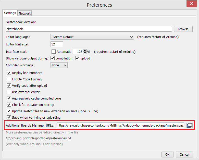
- Start Arduino IDE and press CTRL + comma to select properties.
- Copy and paste the URL below in Additional Boards Manager URLs: text box and click on OK
https://raw.githubusercontent.com/MrBlinky/Arduboy-homemade-package/master/package_arduboy_homemade_index.json
 After this:
- Go to Tools > Boards > Board manager
- In the text box type homemade or Arduboy homemade
- Click on the Arduboy Homemade package and click the Install button.
You can now select Arduboy, Arduboy DevKit and Homemade Arduboy boards from the Tools menu.
This package contains all the currently available Arduboy libraries with changes for homemade Arduboys.
| Arduboy function | Arduboy Leonardo/Micro |
DevelopmentKit | ProMicro 5V (standard wiring) |
ProMicro 5V (alternate wiring) |
|---|---|---|---|---|
| OLED CS | 12 PORTD6 | 6 PORTD7 | GND/(inverted CART_CS)**** | 1/TXO PORTD3* |
| OLED DC | 4 PORTD4 | 4 PORTD4 | 4 PORTD4 | 4 PORTD4 |
| OLED RST | 6 PORTD7 | 12 PORTD6 | 6 PORTD7 | 2 PORTD1* |
| SPI SCK | 15 PORTB1 | 15 PORTB1 | 15 PORTB 1 | 15 PORTB1 |
| SPI MOSI | 16 PORTB2 | 16 PORTB2 | 16 PORTB2 | 16 PORTB2 |
| RGB LED RED | 10 PORTB6 | _ | 10 PORTB6 | 10 PORTB6 |
| RGB LED GREEN | 11 PORTB7 | _ | - | 3 PORTD0* |
| RGB LED BLUE | 9 PORTB5 | 17 PORTB0 | 9 PORTB5 | 9 PORTB5 |
| RxLED | 17 PORTB0 | _ | 17 PORTB0 | 17 PORTB0 |
| TxLED | 30 PORTD5 | _ | 30 PORTD5 | 30 PORTD5 |
| BUTTON UP | A0 PORTF7 | 8 PORTB4 | A0 PORTF7 | A0 PORTF7 |
| BUTTON RIGHT | A1 PORTF6 | 5 PORTC6 | A1 PORTF6 | A1 PORTF6 |
| BUTTON LEFT | A2 PORTF5 | 9 PORTB5 | A2 PORTF5 | A2 PORTF5 |
| BUTTON DOWN | A3 PORTF4 | 10 PORTB6 | A3 PORTF4 | A3 PORTF4 |
| BUTTON A (left) | 7 PORTE6 | A0 PORTF7 | 7 PORTE6 | 7 PORTE6 |
| BUTTON B (right) | 8 PORTB4 | A1 PORTF6 | 8 PORTB4 | 8 PORTB4 |
| SPEAKER PIN 1 | 5 PORTC6 | A2 PORTF5 | 5 PORTC6 | 5 PORTC6 |
| SPEAKER PIN 2 | 13 PORTC7 | A3 PORTF4** | GND | 6 PORTD7* |
| ----------------- | ---------------------- | ----------- | ---------------------------------- | --------------------------------- |
| CART_CS (org) | 0 PORTD2*** | - | 0 PORTD2*** | 0 PORTD2*** |
| CART_CS (new) | 2 PORTD1*** | - | 2 PORTD1*** | - |
| SPI MISO | 14 PORTB3*** | - | - | 14 PORTB3*** |
| ----------------- | ---------------------- | ----------- | ---------------------------------- | --------------------------------- |
| OLED SDA | 4 PORTD4***** | - | 4 PORTD4***** | 4 PORTD4***** |
| OLED SCL | 6 PORTD7***** | - | 6 PORTD7***** | 1/TXO PORTD3***** |
Numbers before the portnames are Arduino assigned pin numbers.
(*) Pro Micro alternate wiring pins:
- PORTD3 OLED CS
- PORTD1 OLED RST
- PORTD7 SPEAKER 2
- PORTD0 RGB LED GREEN
(**) speaker pin 2 output is connected to speaker pin 1 on DevKit hardware. To prevent the IO pins from possible damage, speaker pin 2 should NOT be configured as an output.
(***) Flash cart support (original design) :
- 0 PORTD2 flash cart chip select
- 14 PORTB3 flash cart data in (MISO)
or
Flash cart support (new design) :
- 2 PORTD1/SDA flash cart chip select
- 14 PORTB3 flash cart data in (MISO)
(****) When using serial flash with the Pro Micro standard wiring, OLED_CS (chip select) cannot be grounded (always active). In this case a simple circuit with a general purpose PNP transistor and two resistors or a single inverter chip like the 74LVC1G04 can be used to deactive OLED_CS while CART_CS is active.
(*****) support for I2C displays has been added. When using an I2C display the SDA pin should be connected to pin 4 PORTD4 and the SCL pin to pin 6 PORTD7 unless you're using a Pro Micro with the alternate wiring scherme. In that case SCL pin should be connected to pin 1/TXO PORTD3.
Note that updating a I2C display is slower than a SPI display. To get the most out of an I2C display, the display update code is optimized using assembly and bitbangs the display at 2 Mbps or 2,66 Mbps (uses more progmem).
At 2 Mbps the display update will be 4.3 times slower than when a SPI display is used and 3.1 times slower at 2.66 Mbps. Games will still run smootly at 60 FPS when the main program requires less than %70 (2Mbps) or 78% (2.66Mbps) of MCU power.
An expansion connector can be added to a modified or Homemade Arduboy in the form of a 12 pin male header with 0.1"pitch. which can be used for:
- ICSP header for easy in circuit programming (updating bootloader)
- flash cart slot
- SD card adapter
- infrared communications
- multiplayer link
- sensors
( (Homemade) Arduboy facing top - looking at the male pinheader)
| 12 | 11 | 10 | 9 | 8 | 7 | 6 | 5 | 4 | 3 | 2 | 1 |
|---|---|---|---|---|---|---|---|---|---|---|---|
| TX | RX | SCL | SDA | A5 | KEY | MISO | MOSI | CLK | RST | GND | Vcc |
| 12 | 11 | 10 | 9 | 8 | 7 | 6 | 5 | 4 | 3 | 2 | 1 |
|---|---|---|---|---|---|---|---|---|---|---|---|
| TX | SDA | SCL | RX | A5 | KEY | MISO | MOSI | CLK | RST | GND | Vcc |
(RX and SDA pins are swapped)
TX*  - Serial Transmitter output
RX   - Serial Receiver input / original Flash cart chip select
SCL* - I2C/TWI serial clock I/O
SDA* - I2C/TWI serial data I/O / new Flash cart chip select (Arduboy FX)
A5   - Analog input pin (Note not broken out on Pro Micro boards)
KEY  - Key pin. should be filled to block pin insertion (reverse insert protection)
MISO - SPI/ICSP Master Input, Slave Output
MOSI - SPI/ICSP Master Output, Slave Input
CLK  - SPI/ICSP clock
RST  - MCU/ICSP reset
GND  - Ground (0V)
Vcc  - 5V (~3.0V to ~4.1V on Arduboy)
(*) Not available when using Pro Micro with Alternate Wiring
Note on the original flash cart design RX is used as flash chip select. In the new design (as used by Arduboy FX) SDA is used as flash chip select and Rx and Tx are available for serial comms.


