lshachar / arduino_fanatec_wheel Goto Github PK
View Code? Open in Web Editor NEWA do-it-yourself steering wheel to Fanatec's wheel base
A do-it-yourself steering wheel to Fanatec's wheel base


I'm working on adapting this to my Clubsport V2.5 using an ESP32. I'm a little stumped on the pinout. It seems different from the one provided in the repository. I thought that the Fanatec rims were compatible between the bases. I'm limited in my options since I don't have a Fanatec rim yet. This is what I found so far by probing the base's PCB:

Anyone else take a crack at this yet?
Hi everyone,
first, thank you very much for sharing this very good code basis to interact with Fanatec bases! I had it up and running quite fast and SPI implementation is great!
I'm working on a project to build a custom wheel based on a Podium hub and the fantastic Turn 911 GT3 R 2023 DIY wheel (freely available build up files) (custom wheels based on USB cables or Bluetooth communication did sound a good option to me)
https://www.thingiverse.com/thing:5702348.
As a first step, I tried to find out which Fanatec wheel to replicate to have so many buttons so I tried to identify other wheels and their associated ID in the SPI protocol. Here is the extended list I build :
{0x01} for BMW M3 GT2,
{0x02} for ClubSport FORMULA,
{0x04) for Uni hub
{0x05} X
{0x06} universal hub hub xbox one
{0x07} CSL elite p1 xbox
{0x08} CSL P1 v2 - FW update required
{0x09} Maclaren GT3 v1
{0x0A} clubsport formula v2 / v2.5
{0x0B} Maclaren GT3 v2
{0x0C} Podium hub
{0x0D} not supported
{0x0E} Bentley - FW update required
{0x0F} Podium M4 GT3
{0x10} X
{0x11} CSL universal hub
{0x12} CSL elite WRC
{0x13} BMW GT3 v2
{0x14} X
{0x15} CS universal hub v2
{0x16} CS wheel f1 esports v2
{0x17} Podium BWM m4 GT3
{0x18} and above - nothing
I discovered by the way the so good looking Bentley Fanatec wheel!
For some wheels, my DD1 base required a wheel firmware upgrade to work.
I hope it can help others build their own wheel. I'll post updates here if I can help others.
cheers
Hey!
I've tested this code using an Arduino Nano + Level Shifter and it worked like a charm! As I want to design the smallest possible PCB so that it fits into my Fanatec QR Adapter (52mm to 70mm) I want to use a 3.3V powered Arduino so I don't have to use a level shifter which is quite big.
@lshachar stated that he didn't try a 3.3V Arduino yet, because he thinks that it will be a problem later on if we want to use the buttons. As the button functionality isn't yet fully implemented and I'm planning to use something else this won't bother me. I just need the base to think that a Fanatec rim is attached to it! 😅
I only found a few 3.3V powered Arduino's and made my choice for the Pro Micro.
I have changed the CS_ISR pin to 3, as pin 3 maps to interrup 0 (INT0) on the board. More info about the board can be obtained here.
I've wired everything up and connected it to my base, but it instantly disconnects from my pc and reboots (the rev lights light up and it spins to center itself). So there is definitely something not working as it should.
The strange thing is, if I disconnect pin 4 from the Fanatec QR (5V) and connect the pro micro to my pc via usb to have a look at the serialport, my base does not reconnect if I connect the arduino to it 🤔
The serialport only says that "incoming data crc8 mismatch!" is wrong. I printed the MISO and MOSI buffers and they are:
MOSI:0x00 0x00 0x00 0x00 0x00 0x00 0x00 0x00 0x00 0x00 0x00 0x00 0x00 0x00 0x00 0x00 0x00 0x00 0x00 0x00 0x00 0x00 0x00 0x00 0x00 0x00 0x00 0x00 0x00 0x00 0x00 0x00 0x00
MISO:0xA5 0x03 0x00 0x00 0x00 0x00 0x00 0x00 0x00 0x00 0x00 0x00 0x00 0x00 0x00 0x00 0x00 0x00 0x00 0x00 0x00 0x00 0x00 0x00 0x00 0x00 0x00 0x00 0x00 0x00 0x00 0x13 0x25
Just in case, here is my wiring:
4 - RAW
7 - VCC
3 - GND
5 - GND
1 - 14
2 - 16
6 - 15
8 - 3
Here is the pinout of the Pro Micro as found on the Sparkfun Site:

Please let me know if I can do something else to provide more information that could help to solve the issue. Did maybe one of you already try another 3.3V Arduino, if so did it work for you? I'm not fixed with the pro micro!
Thanks!
When I turn on my CSL Elite + base unit most of the time the Arduino/wheel isn't detected and I have to restart the Arduino with it's reset button after some seconds after turning everything on, then all is well.
I guess it's because the Arduino is booting to fast compared to the wheel base? So I added a one second delay right at the beginning of setup() and now the Arduino/Wheel is detected properly every time I turn on the base unit.
Hello everyone, sorry if this is a stupid question but i was able to get the wheel wired up the only way i've been able to get it to work is by having the Arduino powered up before turning the wheel on. Otherwise when the wheel starts up it instantly disconnects after start.
Hello All,
Has enyone been able to get either the Teensy 3.2 or the Arduino Nano working on a Fanatec CLS Elite V1?
I tried both, but no succes. :(
Regards,
Pistolidas
Any help / hints on that?
Hello @lshachar,
first of all, thx very much for your work, that is just awesome!
I have one question about how to add additional buttons / encoders..
Do i need to change to another wheel than the Porsche RSR? or just modify the button matrix and bytes?
Because as far as i know, i can only use buttons that are originally supported by the wheel? it is like that with thrustmaster
Actually i build sth similar for my previous thrustmaster base and was reading the wheelstates with an arduino sketch by https://rr-m.org/blog/ to implement it into my sketch and simulate the right wheel..
my plan is to use:
3 encoders + push button
8 buttons
so in total i would need to have 19 buttons (wheel states)
any help on where to start?
@EtienneGameSeed As is saw you do not sell the teensy anymore, maybe you can help with some thoughts here without getting too much info away on your own project.
Originally posted by @Shane87F3Ng in #12 (comment)
Hello I wanted to see if you'd be interested in adding a couple alternate schematic images? I edited yours to show an Arduino Uno in place of the nano and also both using a single voltage divider on the MISO line in place of the level shifter.
If you could give them a quick look to make sure I didn't get anything wrong? Then I can issue a pull request if you'd like to add them to the main repository here?
thanks!

*edit I removed the two schematics showing a single voltage divider on the MISO line because I was unable to get my Arduino to read from the wheel base when hooked up as shown. (CRC Error 0x0)
It is entirely possible that the 3v isn't enough for the Uno to recognize even though it should be. I may attempt to add a transistor (pnp222) to feed the Arduino 5v on the MOSI line?
Im trying to get this code to work on an ESP32 and have frustrating results. Occasionally it connects and works exactly as intended. But most of the time, it seems to crash the wheel base (CSL DD) and I need to power cycle the wheelbase.
I also have experienced it working fine, temporarily the computer losing site of the wheel base and then it returning again.
Below is the code I am using to get basic functionality going. I have stripped out almost everything except the emulation of the wheel while I try and solve this problem:
#include <SPI.h>

#define CS_PIN 5
#define DATA_LENGTH 33

uint8_t returnData[DATA_LENGTH] = {
  0xA5, 0x03, 0x00, 0x00, 0x00, 0x00, 0x00, 0x00, 0x48, 0x83, 0x87, 0x47, 0x7B, 0x9A,
  0x79, 0xA0, 0xC9, 0xB5, 0xD8, 0x1D, 0x72, 0x20, 0x2C, 0xFA, 0x62, 0xFF, 0x93, 0x04,
  0xCB, 0x98, 0xD0, 0x12, 0xAF
};
volatile uint32_t sequence = 0;

void cableSelect() {
  if (digitalRead(CS_PIN) == LOW) {  // Check if CS is low
      SPI.transfer(returnData, DATA_LENGTH);  // Send data back to master
  }
}
void setup() {
  pinMode(CS_PIN, INPUT_PULLUP);
  SPI.begin();  // Initialize SPI port
  SPI.setDataMode(SPI_MODE1);  // Set the SPI mode to mode 0
  SPI.setBitOrder(MSBFIRST);  // Set MSB first for data order
  attachInterrupt(digitalPinToInterrupt(CS_PIN), cableSelect, FALLING);  // Attach interrupt for CS pin
}

void loop() {
  // Since the SPI transactions are handled in the ISR, the loop can remain empty
}
I am running out of things to try next and the inconsistency of working vs not working is making it hard to troubleshoot.
Good night all.
With this entry, I just want to thank you for your work. Following your instructions I have been able to simulate a wheel on my CSL DD.
Now I will start performing different tests.
Thank you.

Hello, sorry for maybe stupid question but I would like to ask is this OK to use teensy 3.2 as it's operates at 3.2v instead of arduino with logic shifter?
I know it is far fetched, but worth asking if somebody has done it.
As this great project is using SPI in its core I presume utilizing a PIC Microcontroller would seem feasible. I have some experience with configuring PIC 16F690 to use as Fanatec shifter emulator and presume for here it would be also applicable. This PIC can be powered with 3.3V, has 18 I/O ports, supports SPI and works at 20MHz.
Issue is I am pretty bad as developer and am wondering if somebody worked already on that. I can program the pic to the part that it is SPI Slave and which ports are used for what kind of communication, but the rest is to splice the actual serial communication code from here.
Hey, anybody made this project work with CSL DD?
I couldn't get it to work. I double and triple checked the connections but the only thing happened, was the wheelbase turned off. Also got error message on the TM1637 display.
Hi Ishachar, I used the connection schema (the good one, not mine)
I soldered all wires correctly to the Level Shifter and to the pins. I uploaded the sketch arduino_fanatec_wheel.ino provided on https://github.com/lshachar/Arduino_Fanatec_Wheel/blob/master/arduino_fanatec_wheel.ino
And plugged it in the wheelbase. But no ClubSport Porshe 918 RSR is shown.
Is there something else I have to do? Press the reset button on the Nano or something else?
I also have an Teensy 3.2 with the Teensy code, and that one is working perfectly.
Any help would be appreciated.
Thanks
JonBakhol
Thank you for this amazing project.
I am wondering if it'd be possible to use the "2 cables connectors inside the base to simplify and maybe improve the reliability of the fanatec plug.

These are classic connectors, is there something i'm missing?
Hello, I've connected arduino nano with logic level shifter and this is the message I'm getting, when connecting to serial interface of the arduino. The wheel is acting weird, sometimes it would keep restarting itself, sometimes it works. However, driver software shows Elite steering wheel P1 connected, sometimes it's the BMW one, sometimes Porsche (not sure which type). Also it shows that all the buttons are being pressed randomly.
I have double checked the wiring, but I'll do that again.
I have even used it for a while in ACC, I just had to unmap all the fanatec buttons, as I was getting fake inputs.
Any suggestions? Could it be bad wiring issue? Or maybe bad arduino nano clone?
Unfortunately I don't have any fanatec rim to test out the base, which I bought used. I also have calibration issue, which I thought I fixed after cleaning the sensor, but now it just skips a few degrees of rotation when calibrating - not sure if this could be related, but I assume it's not, as I was getting the crc8 mismatch message even after succesful calibration
Hi, I'm attempting this project without the screen or buttons (I've got another solution for this).
The wheel isn't working, and opening up the serial monitor I am getting the CRC8 mismatch error.
I have looked at my connections with a multimeter - on both sides of the logic level shifter, I'm getting 3.3v and 5v for all pins except L1 and H1, where I'm getting about 0.2v. I presume this is the issue, or is this pin meant to be low?
Dear Ishachar
First of all my congratulations for this project, your work makes this community benefit by adding value and facilitating access to knowledge for all of us who started in this type of project. Congratulations again.
Issues = I followed your instructions to the letter and put together this adapter for a Fanatec CSW 2.5 base. It works almost flawlessly except for two details;
a. when the adapter is in use (after base calibration, up and running) the TM1637 display correctly shows the chosen gear (in game) in the second segment, but randomly and for a very brief moment it also shows in the third segment; there seems to be some problem sending data from the arduino to the TM1637 display. This happens all the time, regardless of the information that the display must show; in fact it doesn't matter if you are in a game or not, the display shows a blinking in the third segment randomly.
b. I have found that by holding pressed any of the gear shift levers (I use the arduino A1 and A2 outputs) the gear changes occur consecutively in ascending or descending order depending on which lever you press; example: I press and hold the lever to shift up and the gear shifts from neutral to 1 and after a very short moment it continues to shift up 2, 3, 4, 5, and 6 (without releasing lever) when it should just shift from neutral to 1 no matter how long you keep the lever pressed. This operation that I describe causes that when you are racing inadvertently two consecutive gears are raised or lowered.
So my question to you is if it is possible to change any parameter or line of code to resolve a. and b. (especially b., which is the most important). I have no programming knowledge, but if you could tell me which line of code and which values to test I would be closer to finding a solution to these issues.
Thank you, greetings from Argentina.
Edited:
So I get mostly CRC8 Match now, but the wheel in the FanaLab still says Not Available, any tips?
Im using Pro Mini 8MHz 3V3. Wired without the 5V pin.
This button does the same as the instruction on the first github page?

I am currently working on making a DIY wheel for my Fanatec base. Looking through the current code and documentation, it appears that there is support for mapping all of the existing buttons from the Fanatec wheels. However, I don't see any mention of the encoders, joysticks, or led rev lights. Most Fanatec wheels have a "funkyswitch" which is a 4-directional d-pad/joystick that also has an encoder built in. Is it possible to add support for that input?
Also, I am currently working on 3d modeling a DIY electrical connector that uses inexpensive header pins so there isn't a need to do the molding using an existing connector,
Hi guys,
I have this thing running on a CSW V2.5, and I cannot turn the wheelbase off by holding the red 'start' button. (I'm assuming it's because that the wheelbase is trying to shut the rim off before powering down, but the rim just keep repeating "Hey! I'm a rim!")
I'm wondering if anyone else has the same problem or not? and what wheelbase are you using?
Thank you.
I guess this should work with DD1 base, has anyone tried it?
In my case, when I connect the arduino to the base, the displays turns off, and I have to power off and on the base to start working again. (just the base, the arduino adapter haven't worked yet)
Any clue?
Thanks for your work! The whole work is great, but for me, after some time of playing, the steering wheel enters the menu by itself. I don't have a d-pad (commented), but I see the s5 on the display after some time. I wonder what is causing it. It's probably due to interference. I was thinking maybe add an extra 'if' in the buttonBitChange() for bit 22 - I don't need menus and calibration, I have a different steering wheel.
Ischachar, in case you don't want confirmed builds for wheelbases other than the one your guide focuses on you can close this or remove it since it's not an issue.
For anyone with a CSL GT Pro and is wondering whether or not this tutorial works for that wheelbase: it does.
I have made one with an Arduino Uno, and a level shifter. The level shifter piggybacks on the Arduino's header pins and uses a DIY'd piece of lane PCB for this, as you can see in the pictures.
It carries 6 direct buttons, and a D-pad with a center-contact (pushing down) that came from an old television, a D-pad I hope to use to navigate game menu's with.
This is all meant to make the wheelbase have Force Feedback because of the Volvo truck wheel attached to the base (through a piece of steel pipe going through a barrel-ball-bearing assembly 50 cm's away from the wheelbase quick connector) because the truck wheel weights around 2,5 kg which I considered to be a bit much).
5 Of the buttons on the Arduino are the 4 cruise control buttons (cruise control on, resume on the left, and increment and decrement the speed set on the right) and the horn button (interconnected, I have thought about making them distinct in order to trigger different types of horns for the games that have this support)
The D-pad is on the underside of the right cruise control button module, and was not originally there in the wheel.

The D-pad required changing the line in code from INPUT to INPUT_PULLUP because values where otherwise to close together.

Hi everyone, I'm currently trying to add a LED strip as a rev display. Therefore, I have to understand which values in the mosiBuf[] contain rpm values. Can anyone help me understand the MOSI buffer? I want to know which cells contain what information, or is there a list of the MOSI bits information so that I can add other support I might need in the future? Any help is greatly appreciated!!!
Have a great weekend :)
Hello Ishachar.
I'm having trouble converting the program to the STM32F4.
I'm still very inexperienced in programming, even more so something created and complex.
I was wondering if you could give me a hand with this question!
In the image there are the initial errors that appear to me, but after defining the pins other errors appear, and after that error it goes back to the lines in red

Hi Ishachar,
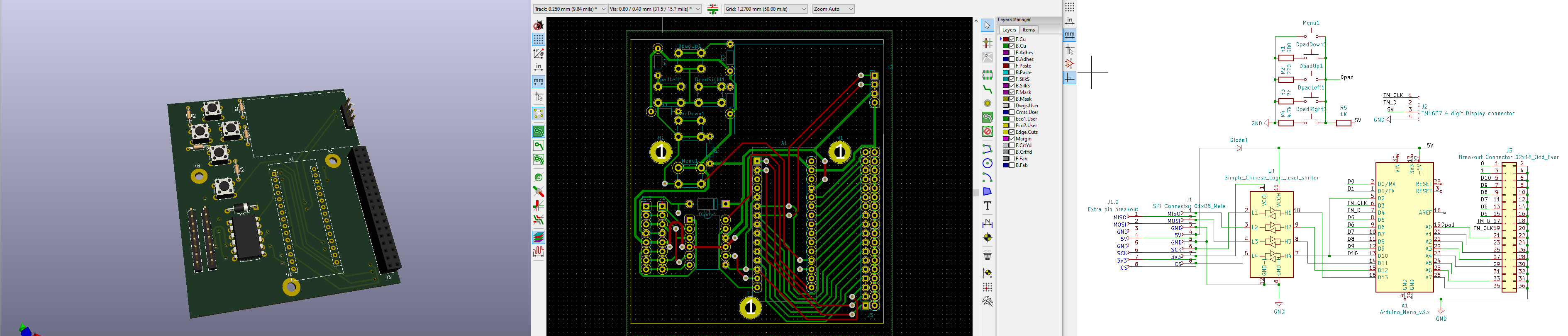
is it possible, that the schematic shown at
is not correct (anymore?)?
Because you connect the 3V3 from the Base to the 3V3 connector on the arduino, but in your detailed schematics, this connection line is not shown. So which one is right? :)
Cheers Shane
Hey all,
I'm currently working on a STM32 implementation.
I'm using a SPI DMA Slave for communication and wanted to try in the first place if the wheel is detected in the software and button presses are recognized.
I've used the data package as mentioned in your sketch.
The wheel is also recognized in the Fanatec Software, but periodically disconnects for a second and then reappears.
I also tried to set some button bits (like in the image), but nether of those were recognized in the control panel.
I've captured the communication with an analyzer, but as far as I can see and understood the protocol, this should be fine

I also cannot see any abnormalities watching the communication over a longer time, that might explain the short disconnects of the wheel.
Any help would be very much appreciated.
Just curious if you have any specific plans using the large gpio connector that you've added to the pcb?
Why I'm wondering is that the delay on using the shifter buttons currently neccesitates a separate solution for the shifter buttons.
A declarative, efficient, and flexible JavaScript library for building user interfaces.
🖖 Vue.js is a progressive, incrementally-adoptable JavaScript framework for building UI on the web.
TypeScript is a superset of JavaScript that compiles to clean JavaScript output.
An Open Source Machine Learning Framework for Everyone
The Web framework for perfectionists with deadlines.
A PHP framework for web artisans
Bring data to life with SVG, Canvas and HTML. 📊📈🎉
JavaScript (JS) is a lightweight interpreted programming language with first-class functions.
Some thing interesting about web. New door for the world.
A server is a program made to process requests and deliver data to clients.
Machine learning is a way of modeling and interpreting data that allows a piece of software to respond intelligently.
Some thing interesting about visualization, use data art
Some thing interesting about game, make everyone happy.
We are working to build community through open source technology. NB: members must have two-factor auth.
Open source projects and samples from Microsoft.
Google ❤️ Open Source for everyone.
Alibaba Open Source for everyone
Data-Driven Documents codes.
China tencent open source team.