mangoiv / draculad Goto Github PK
View Code? Open in Web Editor NEWQMK-powered 34-36 key split keyboard
QMK-powered 34-36 key split keyboard
Hi and thank you sooo much for this great layout!
This is my first built and although I had no experience in soldering anything other than two wires together, I'm careful and like to study in preparation for challenges.
I will not add an OLED or trackball now and will use all the 36 switches as keys, so no rotary encoders also.
I've read your build guide and every other guide/video I could find on DracuLad layout (very few unfortunately). I was about to just ignore the jumpers until I read your comment on #7:
The jumpers can be soldered, even if you don't plan to use an OLED or trackball at that time. It's crucial to solder them on the side the ball/OLED is going on, though, the jumpers basically serve as a way to make the PCB reversible by reversing the pinout corresponding to the jumpers you solder.
Then I thought I'd better ask: What do you mean by "The jumpers can be soldered, even if you don't plan to use..."?
Well... while reading your build guide I noticed the referenced crkbd link for socketing the controller is broken. I searched and found this https://github.com/foostan/crkbd/blob/main/corne-classic/doc/buildguide_en.md which I believe is it(?).
Reading this crkbd buid guide I've found the socketing controller information and also the information below (what you know!?).
To use OLED modules, short circuit the jumper patterns. Only short circuit the front side
Reading this I did not fully understood if I should 1) short circuit as to close each individually, or 2) short circuit them all with each other?
I then inspected the pictures and am pretty positive it's 1: Short circuit jumpers as to close each one individually.


Just for some peace of mind could you please confirm:
Thanks again!!!
PS: I've attached some pictures just because I'm very happy! I've only done one hand diodes and LEDs yet.


Hello,
I ordered a dracuLad kit from littlekeyboards.com and I'm having an issue where the E key is not registering (red circle). I replaced the nearby diode (blue circle) but no luck. I also tried creating a bridge with the nearby keys, but I was unable to get it working.
Once, while fixing the last LED of the right hand side PCB, the e key registered. Unfortunately, I tried the e key after a couple of minutes and it stopped registering.
Do you have any advice as to what could be going wrong/how to fix it? Could it be a manufacturing defect?
Thank you

i can't seem to find the license of this project.
can you please add a "LICENSE"?
Hi, im having trouble getting the trackball to function without having al keys mirrored, im using the right side as the master (there i have the trackball) using qmk cli, not sure if this is a hardware issue with the board as its soldered or a software, could you give me a help?
thanks!
I am confused about how to flash the Micro controller; you reference the QMK guide, but I am not interested in customizing a keymap, I would like whatever defaults you have made, thank you <3
hi, I love this layout but I don't know which of the pcb files I need to open in kicad to create the gerber file.
any tips???
thanks!
Apologies if there is an obvious file with this info but I didn't see it. Does anyone have a PCB Pinout diagram for the controller?
I would like to use a Seeed Studio XIAO NRF52840, which is shorter than a Pro Micro but a 3x5+3 matrix doesn't take many pins. Since I am going wireless/ZMK I don't care about LEDs or trackball and could live without encoders if I had to. If some of the matrix pins are lower down (where they would be missing on my controller) I could wire jumpers, I would just need to know which pins.
Thanks!
This is my first keyboard build, and maybe that's the problem... but I'm familiar with soldering etc..
the pinout isn't clear, so I didn't know the right orientation to put in my Elite-C. Thankfully there's a picture for one side which helped (your not-elite-c that you feature isn't helpful since it doesn't show the pinout on it at all)
Your instructions state to solder in the diodes on the bottom, but it isn't clear where to solder the leds? Is that also the bottom?
You have pictures: acryli_no_caps_top.jpeg that show the diodes soldered to the top?!?!?
I didn't know to be careful about aligning the pins inside the square indicator for the controller, so I've got them on the wrong pins for one of my PCB's (so I'll unsolder it and move it, but it'll be painful).
The main issue I have right now: my LEDS won't turn on. I put them on the top, but I'm guessing that's wrong. I tried putting one on the bottom of the other board... but while it flashed green briefly (when pressed to the contacts), after I soldered it in... it won't turn on at all (note, that's the only one I had put in.
Also, you have pictures of the OLED jumpers filled in without the OLED being installed (acryli_no_caps_top.jpeg), also have pictures of the trackball jumpers filled in... but no trackball. So I'm not sure whether I'm supposed to fill them in or not (I don't have the trackball... yet)
The build guide mentioned: 'for the pimoronis you should not compile the default keymap but rather the "pimoroni" one' but I only see one for DracuLad in QMK Toolbox.
I was wanting to verify if using https://cart.jlcpcb.com/ to make boards would be ok.
What settings/options do you recommend when ordering them (if you are ok with me doing so). Absolutely amazing design.
When I flashed my draculad over a year ago both rotary encoders worked as expected with a customized callback function encoder_update_user(). But when I lately switched to the new qmk setup with separated qmk_firmware and qmk_userspace weird encoder behavior occurred. So I tried the default keymap with
qmk flash --keyboard draculad -km default
on commit qmk/qmk_firmware@1fa84ea
What happens is, that the left encoder works as expected: VOLD/VOLD. But the right encoder has the mirrored assignment (VOLU/VOLD). According to https://github.com/qmk/qmk_firmware/blob/1fa84ea83c68bb24bc6b21c5abc376ee12d1b939/keyboards/draculad/keymaps/default/keymap.c#L201 it should trigger PGDN/PGUP.
I haven't found the reason, yet.
Do you run into the same behavior?
So I built the keyboard and it works except for the trackball that I have on the right side of the board. When I plug in only the right half, the pimoroni works fine, but when I link that to the left half and use the left as the master side it doesn't function.
I saw in the keymap something about commenting out part of the code on the side without the trackball but I'm not sure what exactly I need to do to get it functioning properly, any help would be greatly appreciated.
I'm using the nice!nano with ZMK on my dracuLad.
Everythings working fine except for the encoders. The keypress works but the rotary action does not.
I followed the ZMK docs for enabling encoder support.
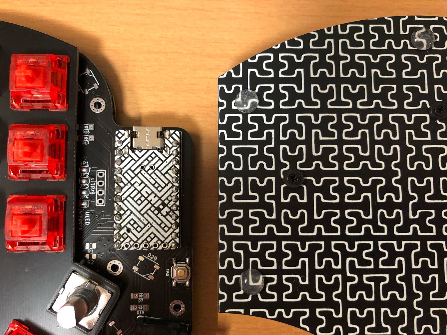
The microcontroller in this image has an awesome design! What is it? Or if that's just a cover of some sort, where can I get one?
A declarative, efficient, and flexible JavaScript library for building user interfaces.
🖖 Vue.js is a progressive, incrementally-adoptable JavaScript framework for building UI on the web.
TypeScript is a superset of JavaScript that compiles to clean JavaScript output.
An Open Source Machine Learning Framework for Everyone
The Web framework for perfectionists with deadlines.
A PHP framework for web artisans
Bring data to life with SVG, Canvas and HTML. 📊📈🎉
JavaScript (JS) is a lightweight interpreted programming language with first-class functions.
Some thing interesting about web. New door for the world.
A server is a program made to process requests and deliver data to clients.
Machine learning is a way of modeling and interpreting data that allows a piece of software to respond intelligently.
Some thing interesting about visualization, use data art
Some thing interesting about game, make everyone happy.
We are working to build community through open source technology. NB: members must have two-factor auth.
Open source projects and samples from Microsoft.
Google ❤️ Open Source for everyone.
Alibaba Open Source for everyone
Data-Driven Documents codes.
China tencent open source team.