USB keyboard to PS/2+AT or XT interface converter using a Raspberry Pi Pico
 |
 |
 |
 |
|---|
Keyboard + Mouse variant: https://github.com/No0ne/ps2x2pico
- Download
ps2pico.uf2orps2pico-XT.uf2from https://github.com/No0ne/ps2pico/releases - Copy
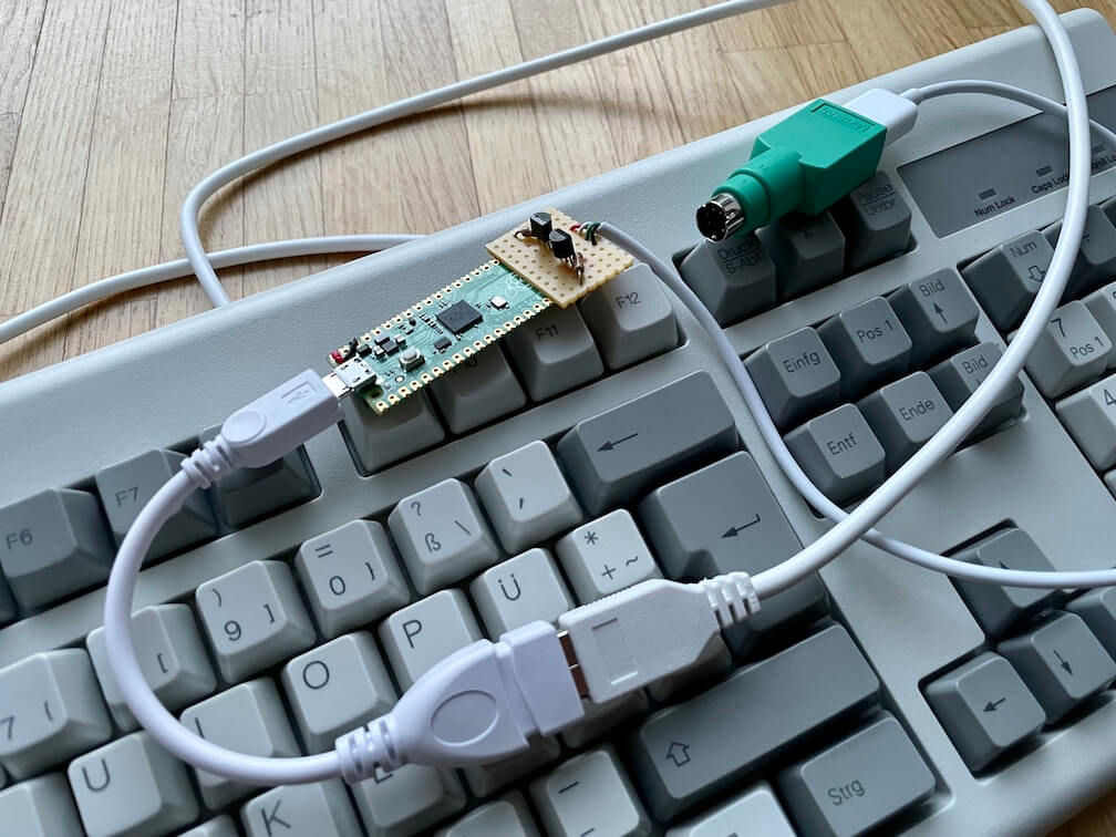
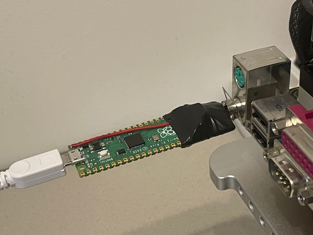
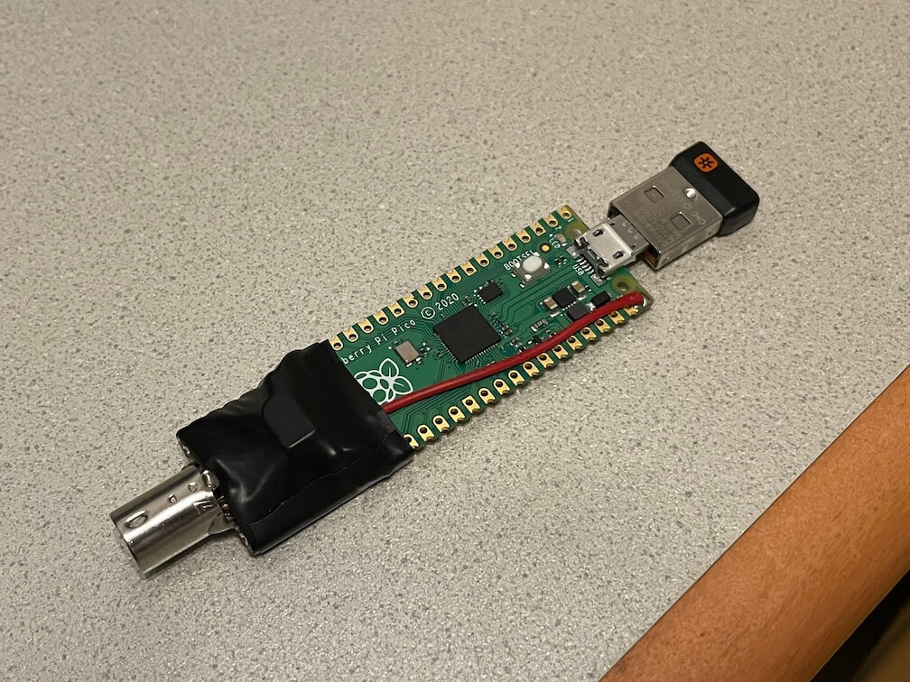
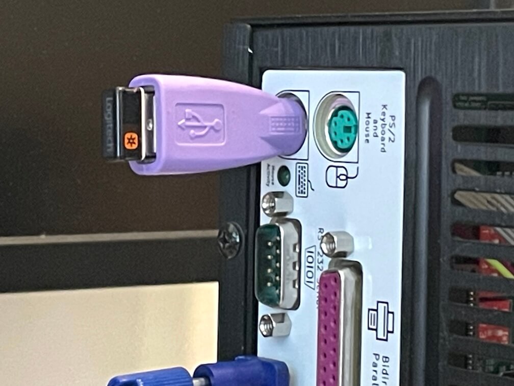
ps2pico.uf2orps2pico-XT.uf2to your Pi Pico by pressing BOOTSEL before pluggging in. - Afterwards connect a USB keyboard using an OTG-adapter and PS/2+AT or XT 5V to Pico VBUS.
- Also works with wireless keyboards with a dedicated USB receiver.
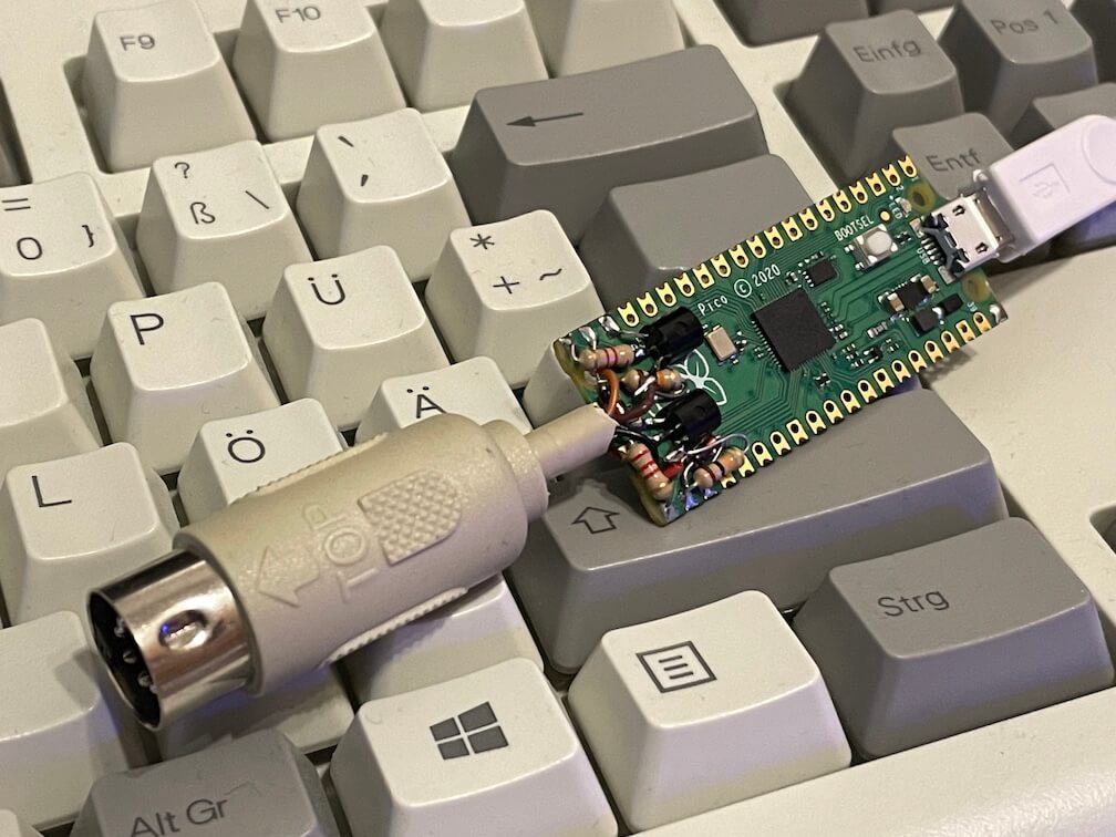
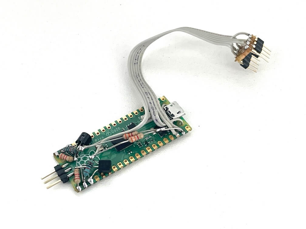
- 3.3V/5V conversion is done with two NPN transistors, two zener diodes and four resistors as shown below:
                 PS/2+AT / XT CLOCK
                       |           ____
                       |__________|10k |___________ GPIO 14
            ____       |          |____|     |
GPIO 15 ___|2k2 |____|/  BC547             __|__
           |____|    |\e                    / \  3V6
                       |                     |
                   ____|__GND________________|___


                 PS/2+AT / XT DATA
                       |          ____
                       |_________|10k |____________ GPIO 17
            ____       |         |____|      |
GPIO 16 ___|2k2 |____|/  BC547             __|__
           |____|    |\e                    / \  3V6
                       |                     |
                   ____|__GND________________|___

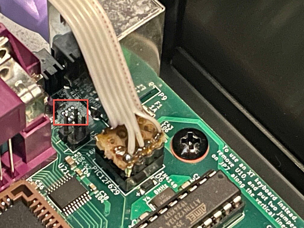
If you have a NuXTv2 you can build an internal version of the ps2pico-XT! Replace U10 with the pico, remove RN13 and add two 4k7 pull-up resistors as shown below:
 |
 |
 |
|---|
export PICO_SDK_PATH=/path/to/pico-sdk
mkdir build
cd build
cmake ..
make
- https://wiki.osdev.org/PS/2_Keyboard
- https://github.com/Harvie/ps2dev/blob/master/src/ps2dev.cpp
- http://www.lucadavidian.com/2017/11/15/interfacing-ps2-keyboard-to-a-microcontroller/
- https://download.microsoft.com/download/1/6/1/161ba512-40e2-4cc9-843a-923143f3456c/translate.pdf
- https://github.com/tmk/tmk_keyboard/wiki/IBM-PC-XT-Keyboard-Protocol
- https://github.com/AndersBNielsen/pcxtkbd/blob/master/XT_KEYBOARD.ino


