SparkFun MOSFET Power Switch and Buck Regulator (Low-Side) (COM-23979)
Does your microcontroller need to control a high-voltage item, like a 12V LED strip, while also needing to be powered? Do you want to avoid having multiple power adapters and microcontrollers for your project? The MOSFET Power Switch and Buck Regulator (Low-Side) is one product we needed at SparkFun, so we figured other folks might have the same problem. Power the board with up to 12V and control up to 10A, all while providing a sweet 3.3V to your control board.
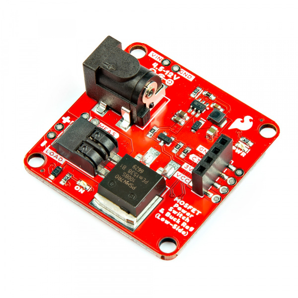
The SparkFun MOSFET Power Switch and Buck Regulator (Low-Side) combines two circuits into one board: an LMR14203 buck regulator configured to output 3.3V and an N-channel MOSFET (PSMN7R0-100BS) configured as a low-side switch. A flyback diode is also on the load side for devices with back EMF! Simply pull the CTL pin low to activate the load.
Various connectors (barrel jack, female header, and poke-home) are provided to connect a power supply to a microcontroller of your choice (Arduino, micro-bit, Raspberry Pi’s microcontroller) and load them together. VCC, 3.3V, CTL, and GND are also broken out through 0.1" spaced PTHs for those who prefer to solder. Two LEDs (PWR_LED and ON_LED) indicate when there is 3.3V and whenever power is applied to the load. Jumpers are included on the back to disable the LEDs. A MEAS PTH jumper is also included for those interested in precisely measuring the current consumption of the system.
Note: While the MOSFET is rated to 100A/100V, we don't recommend you go much above 10A as the PCB polygon pours and traces become the limiter.
- .github/workflows - YAML files used for GitHub Actions and GitHub Pages/mkdocs
-
- /Firmware - Basic example code to control a load with the MOSFET Power Switch and BUck Regulator
- /Hardware - Eagle design files (.brd, .sch)
- /Production - Production panel files (.brd)
- /docs - Online documentation files for GitHub Pages and mkdocs
- /assets - Folder containing all the file assets used for product documentation
- /board_files - Copy of design files used for product documentation
- /component_documentation - Datasheets and manuals for hardware components
- /img - Images for product documentation
- /github - Files stating how to contribute and filing issues for product
- /javascript - Folder containing custom javascript used for product documentation
- /stylesheet - Folder containing CSS files used forproduct documentation
- /assets - Folder containing all the file assets used for product documentation
- /overrides - Customization files used for product documentation
- /.icons - Icons used for product documentation
- ./partials - Used for product documentation
- Fritzing Part
- Hookup Guide - Basic hookup guide for the MOSFET Power Switch and Buck Regulator (Low-Side).
- v1.1 - Initial release
This product is open source!
Please review the LICENSE.md file for license information.
If you have any questions or concerns on licensing, please contact technical support on our SparkFun forums.
Distributed as-is; no warranty is given.
- Your friends at SparkFun.


