thelastoutpostworkshop / gpio_viewer Goto Github PK
View Code? Open in Web Editor NEWGPIOViewer Arduino Library to see live GPIO Pins on ESP32 boards
Home Page: https://youtu.be/JJzRXcQrl3I
License: MIT License
GPIOViewer Arduino Library to see live GPIO Pins on ESP32 boards
Home Page: https://youtu.be/JJzRXcQrl3I
License: MIT License


I tried this lib with existing code that already has wifi enabled in the code. I added the 1st 2 lines of my sketch:
#include <gpio_viewer.h>
GPIOViewer gpio_viewer;
and added as the last line of my setup():
  //init gpioviewer
  gpio_viewer.begin();
Here is the serial output with the errors:
Rebooting...
ESP-ROM:esp32s3-20210327
Build:Mar 27 2021
rst:0xc (RTC_SW_CPU_RST),boot:0x8 (SPI_FAST_FLASH_BOOT)
Saved PC:0x4203be3a
SPIWP:0xee
mode:DIO, clock div:1
load:0x3fce3808,len:0x44c
load:0x403c9700,len:0xbd8
load:0x403cc700,len:0x2a80
entry 0x403c98d0
Test V1.1

assert failed: tcpip_api_call IDF/components/lwip/lwip/src/api/tcpip.c:497 (Invalid mbox)


Backtrace: 0x40377e1a:0x3fceb9c0 0x4037b70d:0x3fceb9e0 0x403817f5:0x3fceba00 0x4201ae39:0x3fcebb30 0x4200a13d:0x3fcebb60 0x42009592:0x3fcebbb0 0x42002bdb:0x3fcebbd0 0x4200340e:0x3fcebc30 0x4200ef9a:0x3fcebc50


ELF file SHA256: fb9bc28191471c18
title says it all
Do you have any plans to allow external developers the ability to contribute to this Repo by way of PRs?
Thanks
Tony
See: https://www.wemos.cc/en/latest/d32/d32.html
and
https://mischianti.org/esp32-wemos-lolin-d32-high-resolution-pinout-and-specs/
Note: you already have the LOLIN32 Lite, this is a later board.
Thank you,
Don.
Can you add this library to platform.io
At the moment I think you are missinglibrary.json which means you can't use this from platform.io
MissingPackageManifestError: Could not find one of 'library.json, library.properties, module.json' manifest files in the package
https://docs.platformio.org/en/latest/manifests/library-json/index.html
I have tested with different programs, analog pins are displayed, but digital pins are not shown.
Is there additional initialization required?
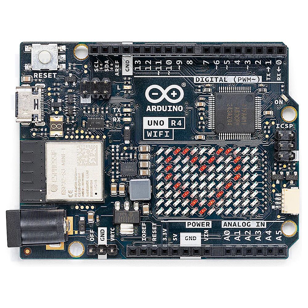
Please add a view for the ESP32-S3 dev module. It is a bit different from the ESP32-S3 WROOM-1 board posted. The best image I have is from the Freenove git-hub (https://github.com/Freenove/Freenove_Basic_Starter_Kit_for_ESP32_S3/blob/main/Datasheet/ESP32-S3%20Pinout.pdf)
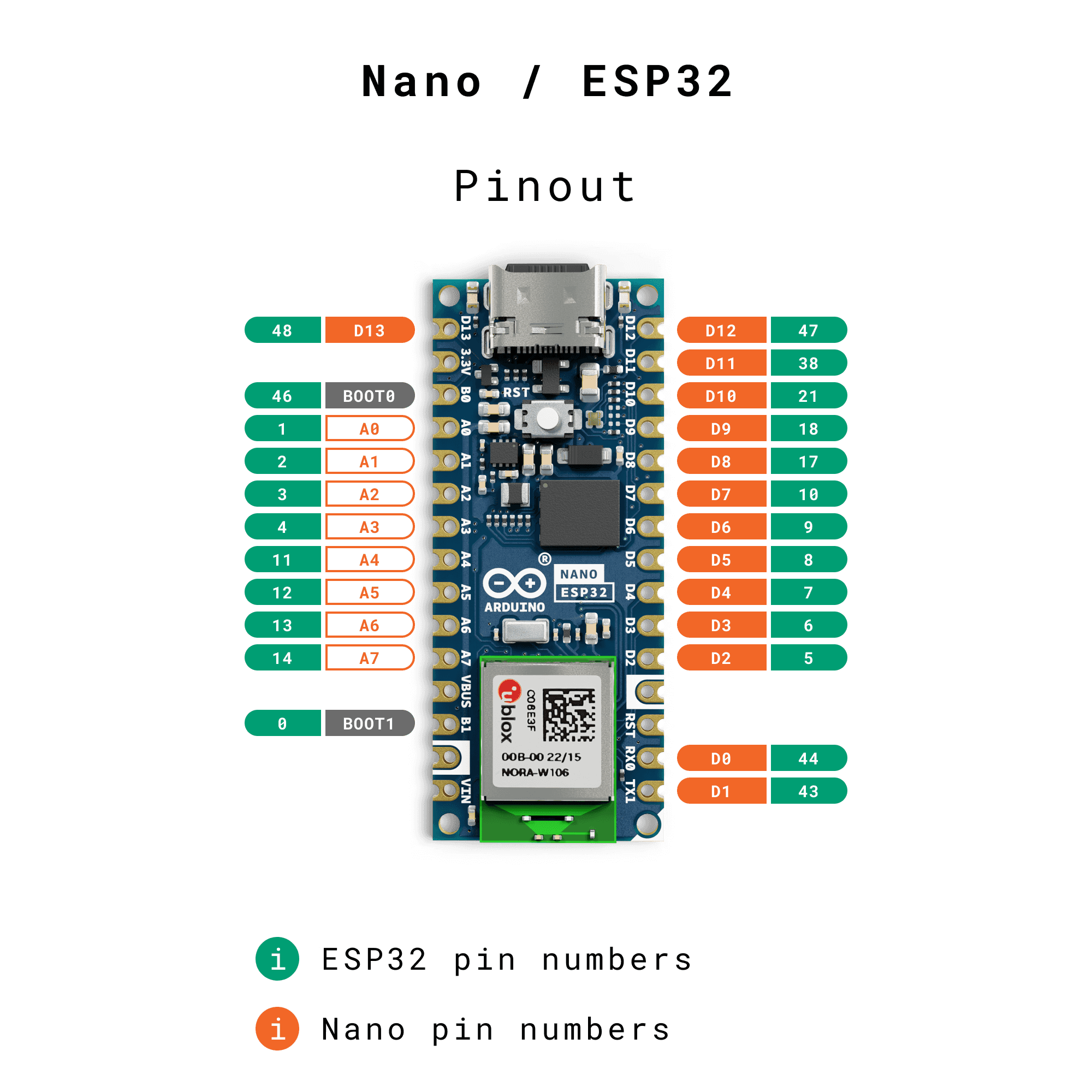
Link to official doc:
https://docs.arduino.cc/hardware/nano-esp32
Would it be possible to enable this within the ESPHome project?
https://www.esphome.io/
I am sorry to say: earlier this week it worked perfectly (using ESP Board 2,0,11.
As a test I left the power on for 24hours.
Now i get this:

I have updated the library to 1,0,5: but the same result.
My test code is:
const int ledPin = 2;
#include <gpio_viewer.h> // Must me the first include in your project
GPIOViewer gpio_viewer;
void setup() {
Serial.begin(115200);
// Comment the next line, If your code already include connection to Wifi
gpio_viewer.connectToWifi("", "*******");
gpio_viewer.setPort(5555);
pinMode(ledPin, OUTPUT); // Initialize GPIO 2 as an output
gpio_viewer.setSamplingInterval(250);
gpio_viewer.begin();
}
void loop() {
digitalWrite(ledPin, HIGH); // Turn on the LED
delay(1000); // Wait for 1 second
digitalWrite(ledPin, LOW); // Turn off the LED
delay(1000); // Wait for 1 second
}
I am very fond to integrate this GPIOVIEWER in many of my projects but I must be sure that it is stable,
I recently came across your video and was inspired to immediately install your library. I'm delighted to report that it worked seamlessly with my TTGO T7 Mini32.
I am writing to kindly request the inclusion of the LILYGO® TTGO T7 Mini32 V1.5 board in your library. Despite my efforts to figure out how to add it myself, it seems that this might not currently be feasible. If possible, I would greatly appreciate any guidance or instructions you could provide on this matter.
For your reference, here are the relevant links:
Homepage: https://www.lilygo.cc/products/t7-mini32-v1-5
GitHub: https://github.com/LilyGO/TTGO-T7-Demo
Thank you for considering my request. I believe that including this board could benefit many users of your library.
Best regards,
Andreas
The code and library work, but it would be nice if the values in analogwrite were also shown, right now the pins set that way always seem to be off
Hello,
there is a lot of issue with this board and the I2C. i would love to be able to debug it with your project.
hope you would get time for it.
thanks for your work !
Please could you add support for this board: https://github.com/Xinyuan-LilyGO/T-Display-S3-AMOLED
Thank you
It would be great if you can integrate the Esp32 S2 Mini V1.0.0 board, thank you very much.

The TinyPICO USB-C board is a ESP32 PICO D4 board from Unexpected Maker in Australia who sells this board worldwide.
All the photos, pinouts & details are here:
Thank you
Tony
I installed the latest release of GPOI viewer (1,0,3)
I installed https://github.com/me-no-dev/ESPAsyncWebServer
I entered in the gpioviewer.ino (= example code) my SSID and Pass
I have added code:
In the setup: pinMode(4, OUTPUT); and digitalWrite(4, LOW);
In the loop: digitalWrite(4, HIGH); delay(1000); digitalWrite(4, LOW); delay(1000);
The Led connected to GPIO is flashing as expected at the rate of 1 sec,
I also restated Arduino,
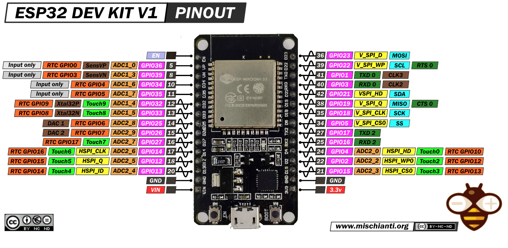
On my browser I see the Picture of the ESP DevKit v1 but ALL pins remain at "0"
What might be the issue???
I use this little board for pretty much all my projects.
Here's a link to a 5-pack, currently on Amazon.
Thanks for this cool library!
Issue is the pin values are not updated when the board selected is changed. If I start with the Generic View then change to ESP32-VROOM-32 board with either 30 or 38 pin the status is not updated until a pin status is changed for all the pins. Seems when different board is selected all the pin values need to be updated for the current state.
Otherwise the code is working great. I can change the sampling interval inside the main LOOP as conditions change.
Thank you.
please give example code to add AsyncElegantOTA and/or webserver along with gpio_viewer
Hello together,
I implementet the viewer in my Code and it works.
But my Projekt has an Wifi Access Point. So i Don#t connect the an WIFI i make my own.
I can reach then the Viewer but it dont show me the states of the Pins.
I think the Problem is that i have an AP.
Can someone help me ?
Console Log:
18:38:04.734 -> Setting AP (Access Point)…AP IP address: 192.168.4.1
18:38:04.843 -> ESP1 added
18:38:04.843 -> ESP2 added
18:38:04.843 -> ESP3 added
18:38:04.843 -> ESP4 added
18:38:04.843 -> HTTP server started
18:38:04.843 -> 0 pins are PWM
18:38:04.843 -> 0 channels are used
18:38:04.843 -> ESP32 is not connected to WiFi.
18:38:04.843 -> Aktive Esps: 4
Sorry for my bad English.
Please add Olimex ESP32-EVB https://gitlab.com/gschorcht/RIOT.wiki-Images/raw/master/esp32/Olimex_ESP32-EVB_pinout.png
Hi, can you please update the "keywords.txt" file (with the below entries), so that all the Class Method colours adjust accordingly in the IDE.
Thanks
Tony
#######################################
#######################################
begin KEYWORD2
setPort KEYWORD2
setSamplingInterval KEYWORD2
connectToWifi KEYWORD2
monitorTaskStatic KEYWORD2
i tried to compile the example. but i got an error
In file included from C:\Users\Dakota\Documents\Arduino\libraries\GPIOViewer\examples\gpioviewer\gpioviewer.ino:8:0:
C:\Users\Dakota\Documents\Arduino\libraries\GPIOViewer\src/gpio_viewer.h: In member function 'int GPIOViewer::readGPIO(int, uint32_t*, pinTypes*)':
C:\Users\Dakota\Documents\Arduino\libraries\GPIOViewer\src/gpio_viewer.h:293:57: error: 'analogGetChannel' was not declared in this scope
uint8_t analogChannel = analogGetChannel(gpioNum);
i tryd to compile it using the Arduino IDE 1.8.13
Hello, great tool, really!
Could you please add another device -> WEMOS LOLIN32 Lite?
https://templates.blakadder.com/wemos_LOLIN32_Lite_v1.html
Hi,
The TinyPICO Nano board is a ESP32 PICO D4 board from Unexpected Maker.
Photos, pinouts & details are here:
https://unexpectedmaker.com/shop.html#!/TinyPICO-Nano/p/578888860/category=154494282
Many thanks
Tony
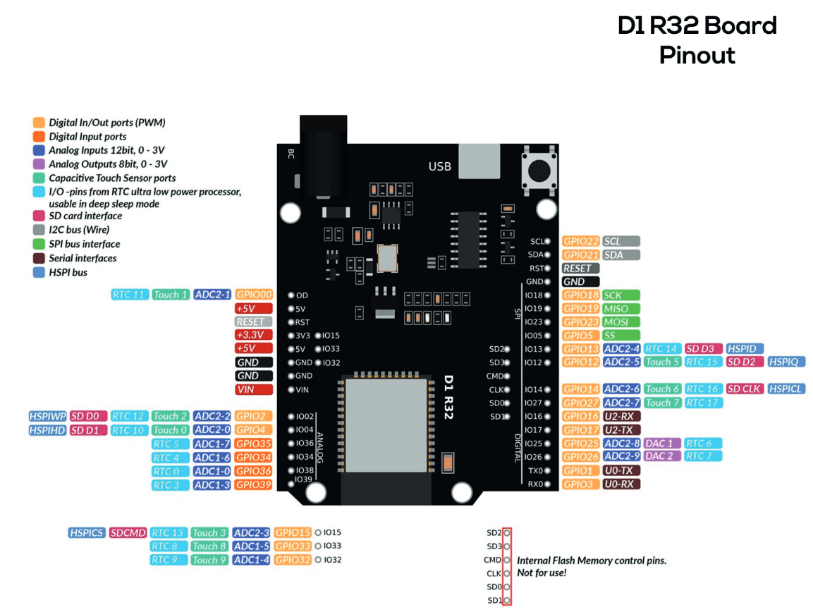
Request addition of the Wemos D1 R32 aka ESPDUINO-32
https://community.platformio.org/t/wemos-d1-r32-any-users/15304
pinout: https://bpb-ap-se2.wpmucdn.com/blogs.auckland.ac.nz/dist/9/698/files/2021/08/2_Pinout_D1_R32.png
This is very cool and I can see where it would be very useful.
Unfortunately, I cannot get it to compile and upload to any of my boards.
The error message I am getting is:
In file included from /gpioviewer/gpioviewer.ino:8:
/Arduino/libraries/GPIOViewer/src/gpio_viewer.h: In member function 'int GPIOViewer::readGPIO(int, uint32_t*, pinTypes*)':
/Arduino/libraries/GPIOViewer/src/gpio_viewer.h:297:22: error: 'GPIO' was not declared in this scope
297 | value = (GPIO.in >> gpioNum) & 0x1;
| ^~~~
/Arduino/libraries/GPIOViewer/src/gpio_viewer.h:302:22: error: 'GPIO' was not declared in this scope
302 | value = (GPIO.in1.val >> (gpioNum - 32)) & 0x1;
| ^~~~
exit status 1
I looked at the gpio_viewer.h and it looks like everything is declared property, but not sure if I am doing something wrong of if there is another issue.
Thank you for creating this project. If you have any suggestion on how to fix this issue, I would appreciate your insight.
I'm following your tutorial, and I have an Arduino nano. When I try to just verify the sample code, I get the following:
I installed the 1.06, ESP Webserver, and the AsyncTCP.
In file included from C:\Users\XXXXXX\OneDrive\Documents\Arduino\gpioviewer\gpioviewer.ino:8:0:
C:\Users\XXXXXX\OneDrive\Documents\Arduino\libraries\GPIOViewer\src/gpio_viewer.h:5:10: fatal error: WebServer.h: No such file or directory
 #include <WebServer.h>
          ^~~~~~~~~~~~~
compilation terminated.

exit status 1
Image: https://github.com/PIBSAS/GPView/blob/main/gpio_viewer/assets/devboards_images/ESP32-WROOM-32D.png
Pinout is the same that you have like VROOM, and this is part of same pinout for various ESP32 DevKitC: https://www.espressif.com/en/products/devkits
For the microcontrollers but with different pics:
https://docs.espressif.com/projects/esp-idf/en/latest/esp32/hw-reference/esp32/get-started-devkitc.html
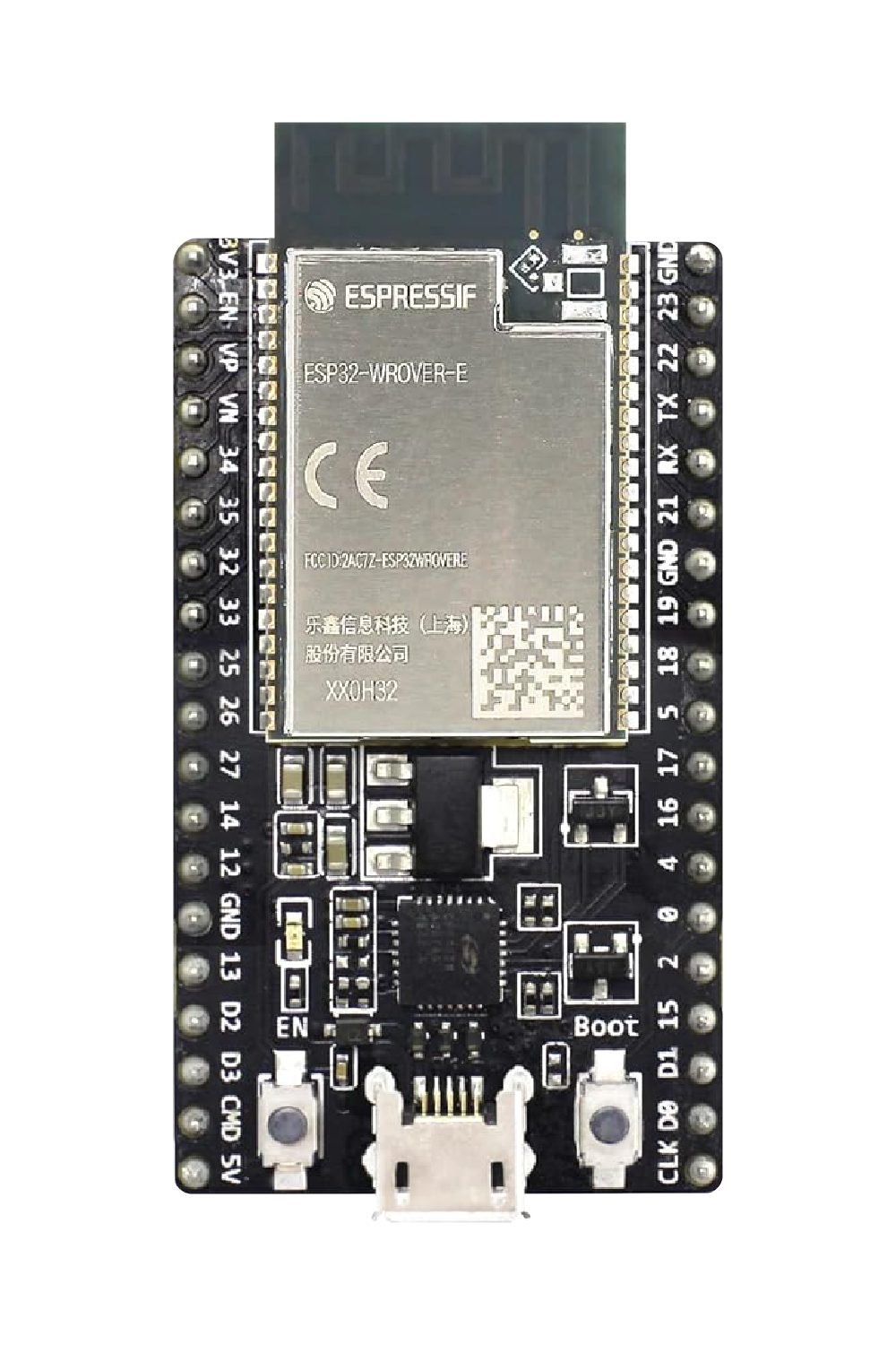
ESP32-WROOM-32E
ESP32-WROOM-32UE
ESP32-WROOM-DA
ESP32-WROVER-E (This is show in the Product selector, the rest on the docs.https://www.espressif.com/sites/default/files/dev-board/ESP32-DevKitC_L_0.png)
ESP32-WROVER-IE
More Pics newer boards:
https://docs.espressif.com/projects/espressif-esp-dev-kits/en/latest/
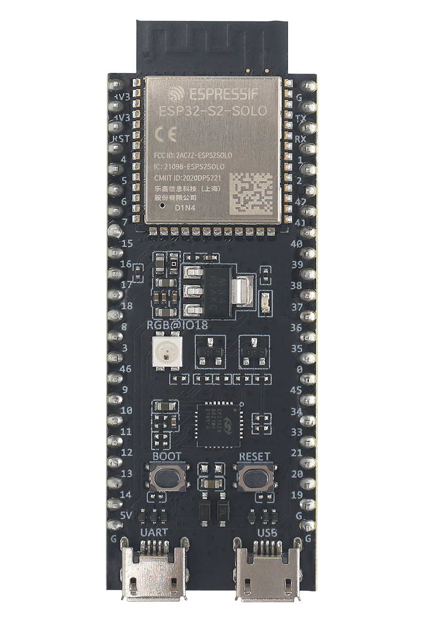
#ESP32-S2-DevKitC-1/ESP32-S3-SOLO
https://www.espressif.com/sites/default/files/dev-board/ESP32-S2-DevKitC-1%20large.png
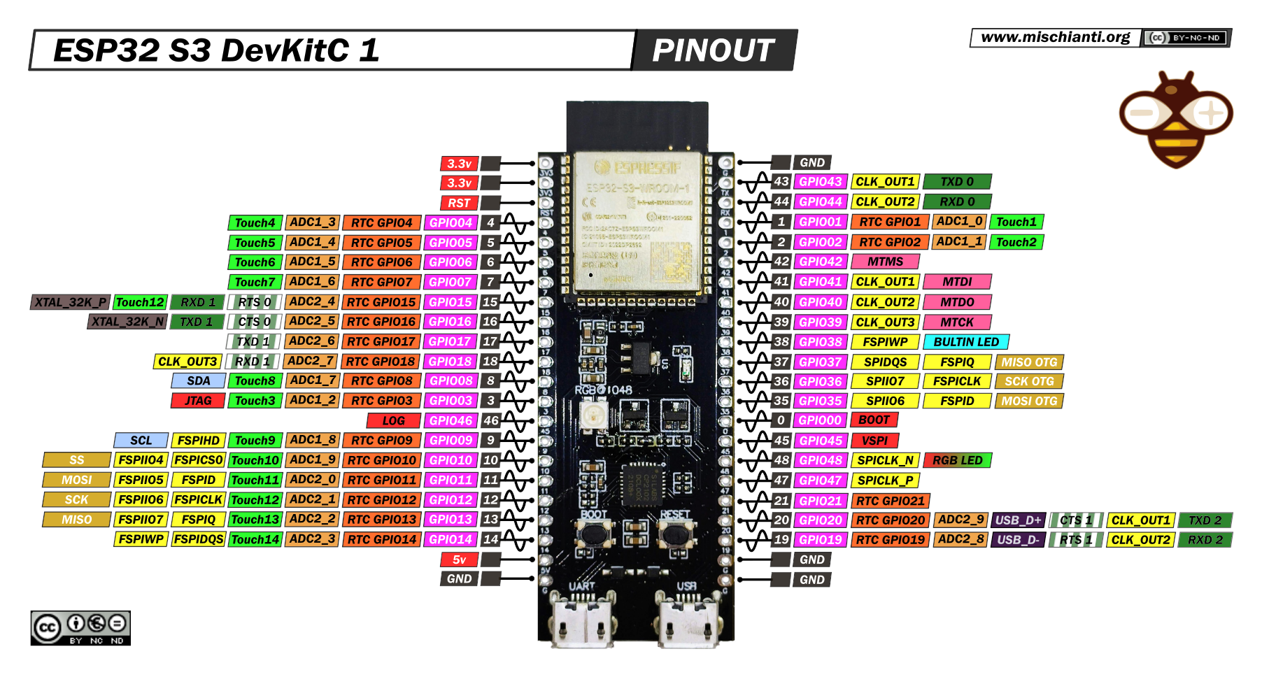
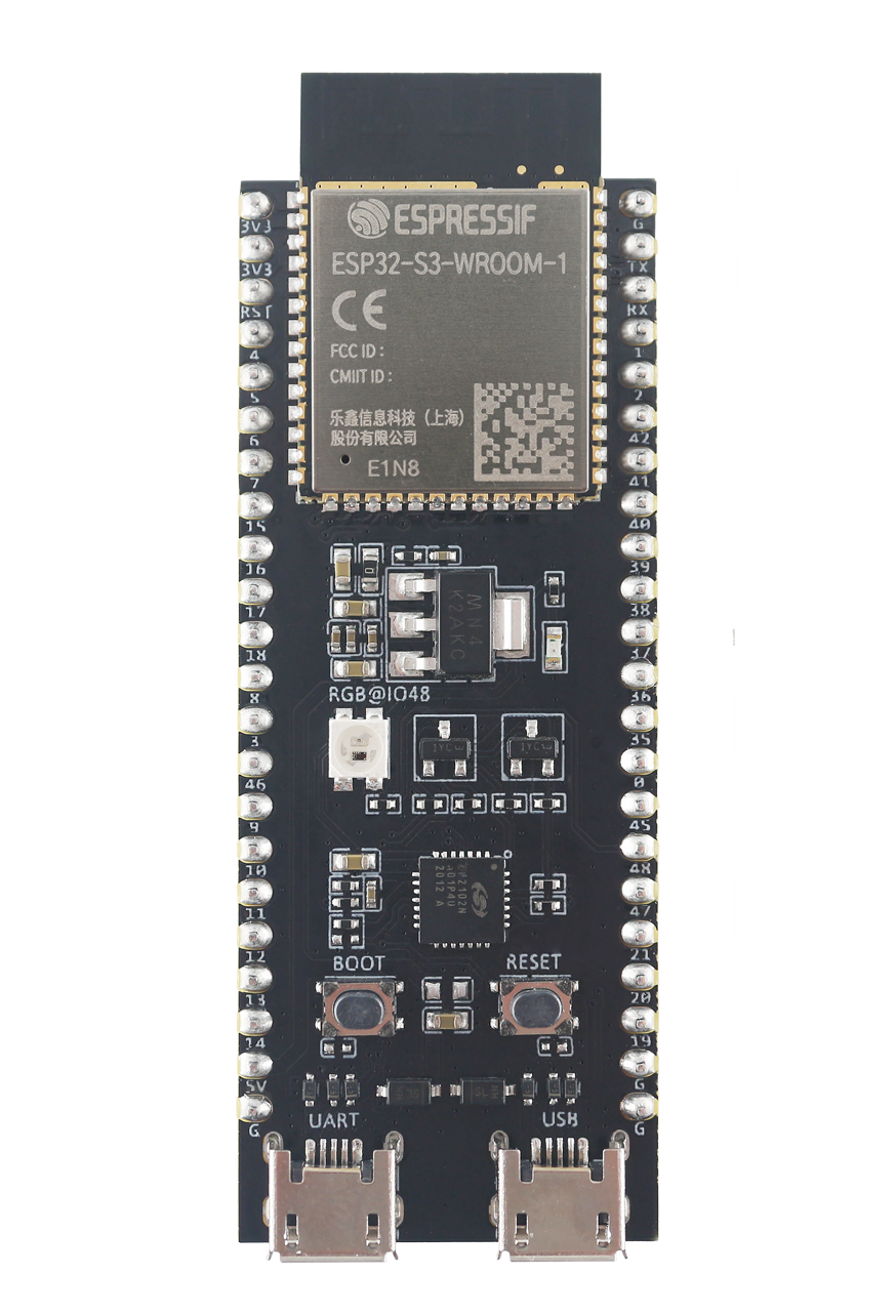
#ESP32-S3-WROOM-1(MicroUSB) DevKitC1:
Pinout: https://mischianti.org/wp-content/uploads/2023/06/esp32-S3-DevKitC-1-original-pinout-high.png
Image:
https://www.espressif.com/sites/default/files/dev-board/ESP32-S3-DevKitC-1%20%E5%A4%A7.png
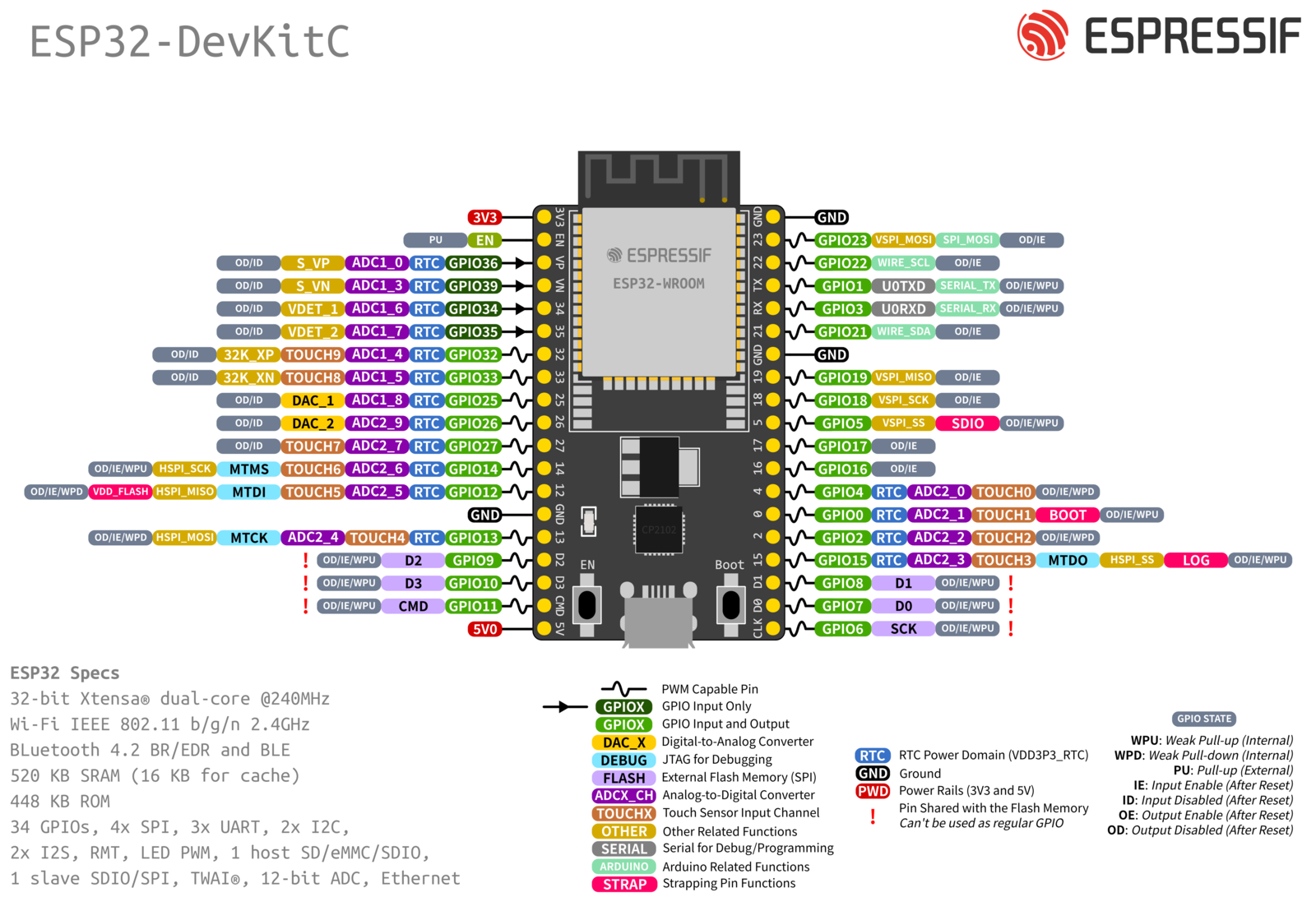
html for ESP32-DevKitC_S_0.png:
<div id="indicators">
  <div class="indicator" style="top: 26.666%; left: 21.6%" id="gpio36"></div>
  <div class="indicator" style="top: 30.466%; left: 21.6%" id="gpio39"></div>
  <div class="indicator" style="top: 34.266%; left: 21.6%" id="gpio34"></div>
  <div class="indicator" style="top: 38.066%; left: 21.6%" id="gpio35"></div>
  <div class="indicator" style="top: 41.866%; left: 21.6%" id="gpio32"></div>
  <div class="indicator" style="top: 45.666%; left: 21.6%" id="gpio33"></div>
  <div class="indicator" style="top: 49.466%; left: 21.6%" id="gpio25"></div>
  <div class="indicator" style="top: 53.266%; left: 21.6%" id="gpio26"></div>
  <div class="indicator" style="top: 57.066%; left: 21.6%" id="gpio27"></div>
  <div class="indicator" style="top: 60.866%; left: 21.6%" id="gpio14"></div>
  <div class="indicator" style="top: 64.666%; left: 21.6%" id="gpio12"></div>
  <div class="indicator" style="top: 72.266%; left: 21.6%" id="gpio13"></div>
  <div class="indicator" style="top: 76.066%; left: 21.6%" id="gpio9"></div>
  <div class="indicator" style="top: 79.866%; left: 21.6%" id="gpio10"></div>
  <div class="indicator" style="top: 83.666%; left: 21.6%" id="gpio11"></div>

  <div class="indicator" style="top: 22.866%; left: 78.4%" id="gpio23"></div>
  <div class="indicator" style="top: 26.666%; left: 78.4%" id="gpio22"></div>
  <div class="indicator" style="top: 30.466%; left: 78.4%" id="gpio1"></div>
  <div class="indicator" style="top: 34.266%; left: 78.4%" id="gpio3"></div>
  <div class="indicator" style="top: 38.066%; left: 78.4%" id="gpio21"></div>
  <div class="indicator" style="top: 41.866%; left: 78.4%" id="gpio23"></div>
  <div class="indicator" style="top: 45.666%; left: 78.4%" id="gpio19"></div>
  <div class="indicator" style="top: 49.466%; left: 78.4%" id="gpio18"></div>
  <div class="indicator" style="top: 53.266%; left: 78.4%" id="gpio5"></div>
  <div class="indicator" style="top: 57.066%; left: 78.4%" id="gpio17"></div>
  <div class="indicator" style="top: 60.866%; left: 78.4%" id="gpio16"></div>
  <div class="indicator" style="top: 64.666%; left: 78.4%" id="gpio4"></div>
  <div class="indicator" style="top: 68.466%; left: 78.4%" id="gpio0"></div>
  <div class="indicator" style="top: 72.266%; left: 78.4%" id="gpio2"></div>
  <div class="indicator" style="top: 76.066%; left: 78.4%" id="gpio15"></div>
  <div class="indicator" style="top: 79.866%; left: 78.4%" id="gpio8"></div>
  <div class="indicator" style="top: 83.666%; left: 78.4%" id="gpio7"></div>
  <div class="indicator" style="top: 87.466%; left: 78.4%" id="gpio6"></div>

  <div id="values">
    <div class="value value_right" style="top: 25.566%; left: -5%" id="gpio36">0</div>
    <div class="value value_right" style="top: 29.366%; left: -5%" id="gpio39">0</div>
    <div class="value value_right" style="top: 33.166%; left: -5%" id="gpio34">0</div>
    <div class="value value_right" style="top: 37.066%; left: -5%" id="gpio35">0</div>
    <div class="value value_right" style="top: 40.766%; left: -5%" id="gpio32">0</div>
    <div class="value value_right" style="top: 44.566%; left: -5%" id="gpio33">0</div>
    <div class="value value_right" style="top: 48.366%; left: -5%" id="gpio25">0</div>
    <div class="value value_right" style="top: 52.166%; left: -5%" id="gpio26">0</div>
    <div class="value value_right" style="top: 56.066%; left: -5%" id="gpio27">0</div>
    <div class="value value_right" style="top: 59.766%; left: -5%" id="gpio14">0</div>
    <div class="value value_right" style="top: 63.566%; left: -5%" id="gpio12">0</div>
    <div class="value value_right" style="top: 71.166%; left: -5%" id="gpio13">0</div>

    <div class="value" style="top: 21.766%; left: 84%" id="gpio23">0</div>
    <div class="value" style="top: 25.566%; left: 84%" id="gpio22">0</div>
    <div class="value" style="top: 29.366%; left: 84%" id="gpio1">0</div>
    <div class="value" style="top: 33.166%; left: 84%" id="gpio3">0</div>
    <div class="value" style="top: 37.066%; left: 84%" id="gpio21">0</div>
    <div class="value" style="top: 44.566%; left: 84%" id="gpio19">0</div>
    <div class="value" style="top: 48.366%; left: 84%" id="gpio18">0</div>
    <div class="value" style="top: 52.166%; left: 84%" id="gpio5">0</div>
    <div class="value" style="top: 56.066%; left: 84%" id="gpio17">0</div>
    <div class="value" style="top: 59.766%; left: 84%" id="gpio16">0</div>
    <div class="value" style="top: 63.566%; left: 84%" id="gpio4">0</div>
    <div class="value" style="top: 67.366%; left: 84%" id="gpio0">0</div>
    <div class="value" style="top: 71.166%; left: 84%" id="gpio2">0</div>
    <div class="value" style="top: 75.066%; left: 84%" id="gpio15">0</div>
  </div>

  <div class="stats" style="top: 58%; left: 30%" id="freeHeap">Free Heap: 142.10 KB</div>
  <div class="stats" style="top: 64%; left: 30%" id="freeRAM">Free Sketch: 1.25 MB</div>
</div>
Thanks for library, i've use Color Picker online to get pixels on PNG then look for porcentage, maybe is not the smartest way he, but in the image of my board ESP32-WROOM-32D the dots are more oval and i dont know how to fix that. Hope soon your library be in Library Manager, nice work!
Info and Image can be found here
https://heltec.org/project/wireless-stick-lite-v2/
Thank you so much.
Love the library. Would love support for the ESP32 WROOM-32 boards. Similar looking to the ESP32-VROOM-32D but with different pinout.


Thanks.
I tried to get it running with PlatformIO, but am having issues, mostly due to ESPAsyncWebServer dependencies
It would great if this could be published as a PlatformIO Library to be included from the Libraries manager.
Also, as a side note, ESPAsyncWebServer seems to be abandoned, but there is another project that is active and compatible, and already available on PlatformIO as well, https://github.com/hoeken/PsychicHttp
PsychicHttp appears to be a re-implemented and lighter version of what ESPAsyncWebServer is.
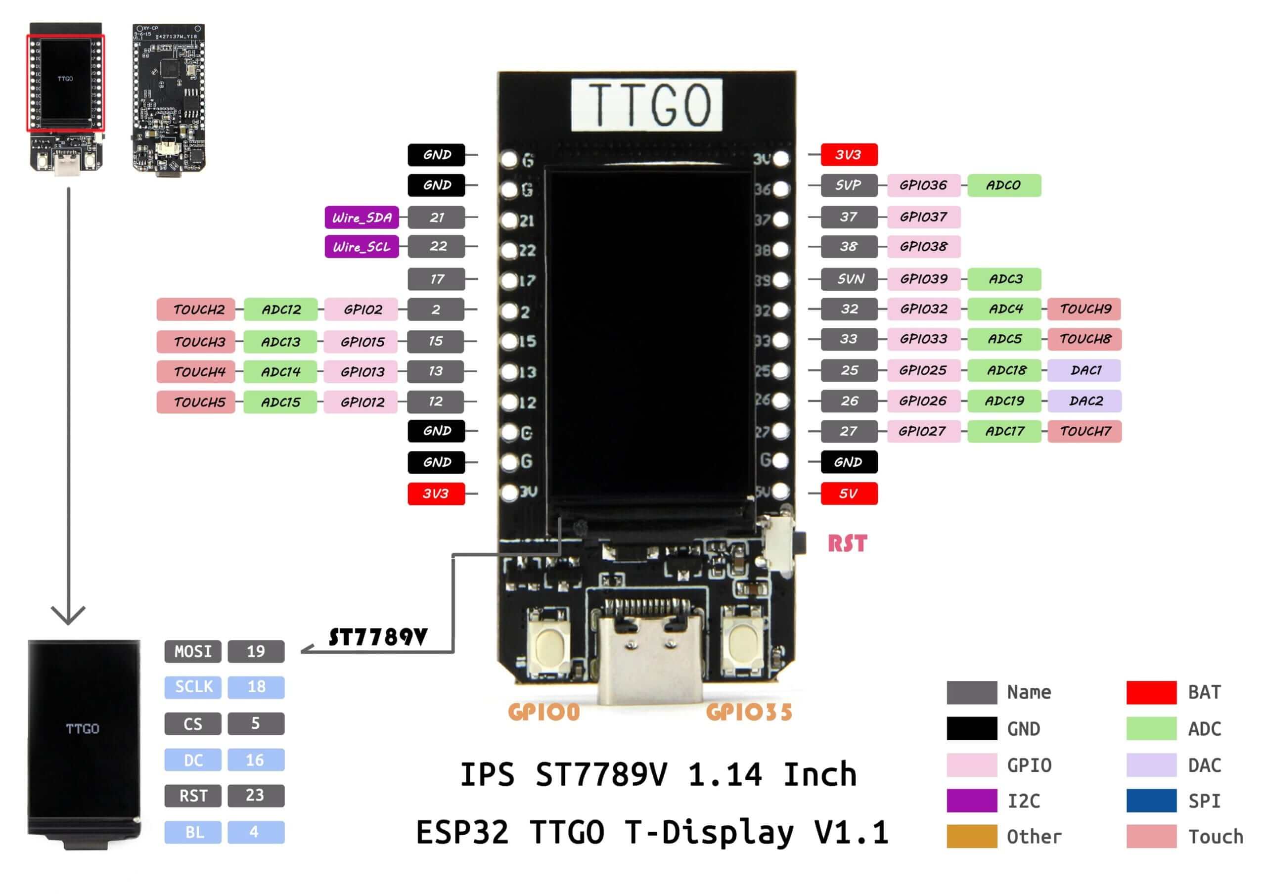
Would appreciate getting this slightly older board added.
https://uelectronics.com/wp-content/uploads/2020/10/Esquematico-TTGO-T-Display-ESP32-scaled.jpg
Is it possible to view analogue input values of pins? they currently show as zero.
Amazing project BTW, thank you !
Hi,
Thank you for this great project.
Can you please this board: https://www.amazon.com/CANADUINO-WEMOS-Minikit-240MHz-Bluetooth/dp/B07KWHRM5R
thank you so much .
is:issue is:open Please add OLIMEX ESP32-POE - its ESP32+Ethernet board. The data are here https://www.olimex.com/Products/IoT/ESP32/ESP32-POE/open-source-hardware
Hi,
Looks like awsome project, tried it, I see the web page but no blinking led, all gpios are constatntly off.
this is my code:
/***
This example is intended to demonstrate the use of the GPIO Viewer Library.
Tutorial : https://youtu.be/UxkOosaNohU
Documentation : https://github.com/thelastoutpostworkshop/gpio_viewer
***/
#include <gpio_viewer.h> // Must me the first include in your project
GPIOViewer gpio_viewer;
void setup()
{
Serial.begin(115200);
// Comment the next line, If your code aleady include connection to Wifi
gpio_viewer.connectToWifi("ssid", "pass");
// gpio_viewer.setPort(5555); // You can set the http port, if not set default port is 8080
// Your own setup code start here
pinMode(2, OUTPUT);
digitalWrite(2, HIGH); // turn the LED on
// Must be at the end of your setup
// gpio_viewer.setSamplingInterval(25); // You can set the sampling interval in ms, if not set default is 100ms
gpio_viewer.begin();
}
// You don't need to change your loop function
void loop() {
digitalWrite(2, HIGH); // turn the LED on
delay(500); // wait for 500 milliseconds
digitalWrite(2, LOW); // turn the LED off
delay(500);
}
// The rest of your code here

This gpio_viewer is awesome!! but when I add my code it will not load the web-viewer. Response is refused to connect.
My ESP32 is 30 pin Wroom.
#include <gpio_viewer.h> // Must me the first include in your project for ESP32 GPIO Monitoring
GPIOViewer gpio_viewer;
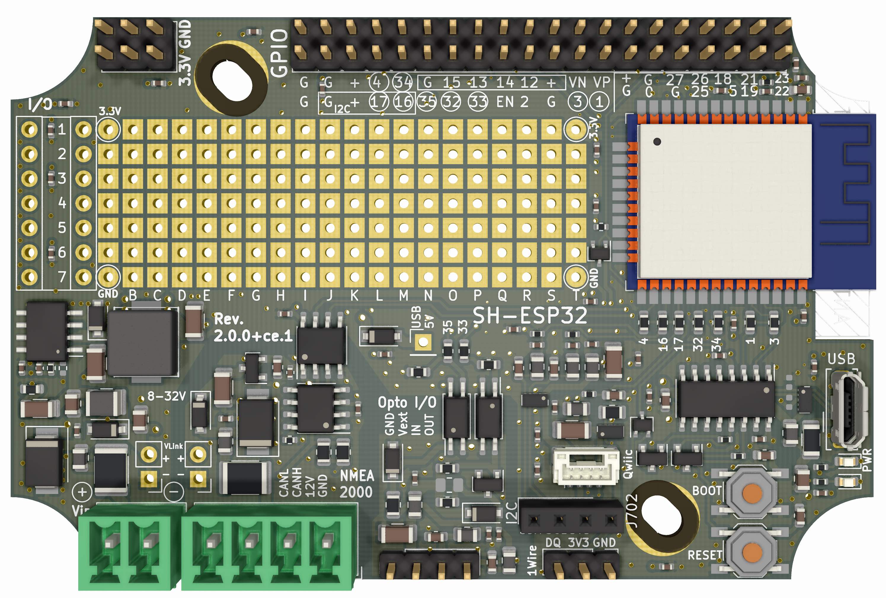
// --- shield pins ---------------------
#define SHIELD_LED_PIN 26
#define SHIELD_CAN_RX GPIO_NUM_5
#define SHIELD_CAN_TX GPIO_NUM_4
#define SHIELD_VOLTAGE_DIVIDER 32 /* the jumper must be soldered on the v1.1 shield. Voltage divider doesn't work/exist on v1.0 */
//#define CAN_FRAME CAN.write
// --- can ---------------------------
#include <esp32_can.h> /* https://github.com/collin80/esp32_can */
void printFrame(CAN_FRAME *message)
{
Serial.print(message->id, HEX);
if (message->extended) Serial.print(" X ");
else Serial.print(" S ");
Serial.print(message->length, DEC);
for (int i = 0; i < message->length; i++) {
Serial.print(message->data.byte[i], HEX);
Serial.print(" ");
}
Serial.println();
}
void gotHundred(CAN_FRAME *frame)
{
Serial.print("Got special frame! ");
printFrame(frame);
}
void setup() {
// put your setup code here, to run once:
Serial.begin(115200);
// --- ESP32 GPIO VIEWER ---------------------------
gpio_viewer.connectToWifi("address removed", "password removed"); // Comment the next line, If your code already include connection to Wifi
gpio_viewer.setPort(8080); // You can set the http port, if not set default port is 8080
// --- ESP32 GPIO VIEWER ---------------------------
Serial.println("Initializing ...");
Serial.println("------------------------");
Serial.println(" MrDIY SENDER CAN SHIELD");
Serial.println("------------------------");
CAN0.setCANPins(GPIO_NUM_5, GPIO_NUM_4);
if(CAN0.begin(500000))
{
Serial.println(" CAN...............INIT");
} else {
Serial.println("Init Failed ...");
}
Serial.println("Ready ...!");
CAN_FRAME txFrame;
txFrame.rtr = 0;
txFrame.id = 0x215;
txFrame.extended = false;
txFrame.length = 4;
txFrame.data.uint8[0] = 0x10;
txFrame.data.uint8[1] = 0x1A;
txFrame.data.uint8[2] = 0xFF;
txFrame.data.uint8[3] = 0x5D;
CAN0.sendFrame(txFrame);
pinMode(SHIELD_LED_PIN, OUTPUT);
digitalWrite(SHIELD_LED_PIN, LOW);
CAN0.watchFor(); //then let everything else through anyway
// --- ESP32 GPIO VIEWER ---------------------------
// Must be at the end of your setup
// gpio_viewer.setSamplingInterval(25); // You can set the sampling interval in ms, if not set default is 100ms
gpio_viewer.begin();
}
void loop() {
byte i=0;
// CAN message frame
CAN_FRAME message;
// put your main code here, to run repeatedly:
Serial.print("Sending packet ... ");
//or, just plain send traffic periodically
delayMicroseconds(200);
message.id++;
message.length = 8;
for(i=0;i<message.length;i++) {
 message.data.uint8[i]++;
}
CAN0.sendFrame(message);
Serial.println("done");
}
A declarative, efficient, and flexible JavaScript library for building user interfaces.
🖖 Vue.js is a progressive, incrementally-adoptable JavaScript framework for building UI on the web.
TypeScript is a superset of JavaScript that compiles to clean JavaScript output.
An Open Source Machine Learning Framework for Everyone
The Web framework for perfectionists with deadlines.
A PHP framework for web artisans
Bring data to life with SVG, Canvas and HTML. 📊📈🎉
JavaScript (JS) is a lightweight interpreted programming language with first-class functions.
Some thing interesting about web. New door for the world.
A server is a program made to process requests and deliver data to clients.
Machine learning is a way of modeling and interpreting data that allows a piece of software to respond intelligently.
Some thing interesting about visualization, use data art
Some thing interesting about game, make everyone happy.
We are working to build community through open source technology. NB: members must have two-factor auth.
Open source projects and samples from Microsoft.
Google ❤️ Open Source for everyone.
Alibaba Open Source for everyone
Data-Driven Documents codes.
China tencent open source team.

