Giter Site home page Giter Site logo

viveris / jtag-boundary-scanner Goto Github PK

View Code? Open in Web Editor NEW
117.0 22.0 33.0 366 KB

JTAG boundary scan debug & test tool.

License: GNU General Public License v3.0

Makefile 2.34% C 97.55% Shell 0.11%
jtag boundary-scan jtag-boundary-scan debug tool jtag-probe

jtag-boundary-scanner's Introduction

JTAG Boundary Scanner logo

JTAG Boundary Scanner

JTAG Boundary-scan board debugging/test software

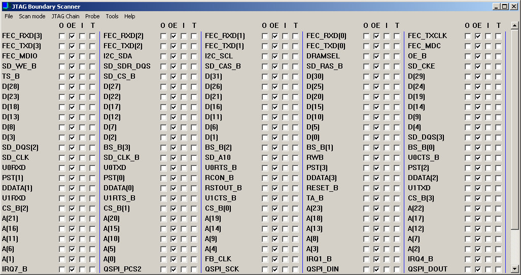
The JTAG Boundary Scanner is a JTAG software tool to debug or test any electronic boards with a JTAG interface.

JTAG Boundary Scanner software

Main characteristics and features

  • Windows version GUI.

  • Implemented in C.

  • BSDL files support.

  • Target IO pins sampling and control mode ( SAMPLE & EXTEST ).

  • I2C Bus over JTAG emulation.

  • SPI Bus over JTAG emulation.

  • MDIO Bus over JTAG emulation.

  • Parallel port bus over JTAG emulation.

  • JTAG Bus scan and devices auto-detection.

  • BSDL files auto-load.

  • script support.

  • socket interface for remote control.

Supported Probes

  • FTDI FT2232H based JTAG probes support (Olimex ARM-USB_OCD-H, Lattice HW-USBN-2B, Xilinx...).

  • JLINK JTAG probes support. Note : JLinkARM.dll need to be copied into the JTAGBoundaryScanner folder for the JLink probes support.

  • Parallel port based JTAG probes support (Altera ByteBlaster, Memec IJC-4, Macgraigor Wiggler).

License

This project is licensed under the GNU General Public License version 3 - see the LICENSE file for details

jtag-boundary-scanner's People

Contributors

jfdelnero avatar scorbeau avatar

Stargazers

 avatar  avatar  avatar  avatar  avatar  avatar  avatar  avatar  avatar  avatar  avatar  avatar  avatar  avatar  avatar  avatar  avatar  avatar  avatar  avatar  avatar  avatar  avatar  avatar  avatar  avatar  avatar  avatar  avatar  avatar  avatar  avatar  avatar  avatar  avatar  avatar  avatar  avatar  avatar  avatar  avatar  avatar  avatar  avatar  avatar  avatar  avatar  avatar  avatar  avatar  avatar  avatar  avatar  avatar  avatar  avatar  avatar  avatar  avatar  avatar  avatar  avatar  avatar  avatar  avatar  avatar  avatar  avatar  avatar  avatar  avatar  avatar  avatar  avatar  avatar  avatar  avatar  avatar  avatar  avatar  avatar  avatar  avatar  avatar  avatar  avatar  avatar  avatar  avatar  avatar  avatar  avatar  avatar  avatar  avatar  avatar  avatar  avatar  avatar  avatar

Watchers

 avatar  avatar  avatar  avatar  avatar  avatar  avatar  avatar  avatar  avatar  avatar  avatar  avatar  avatar  avatar  avatar  avatar  avatar  avatar  avatar  avatar  avatar

jtag-boundary-scanner's Issues

User manual?

Hi, I'd like to ask if there are any user manuals/guides/examples/tutorials that can help me learn this tool? Right now I've only found docs/scripts/script_engine_test.txt which seems to be a list script commands the scanner can accept, and a lib_jtag_core/src/config.script which I'm still trying to figure out. I also failed to find documentation on the Internet. Any help? Thanks!

Help with generic FT2232H adapter

Hi, I was trying to use your tool with a generic FT2232H breakout board. The board is detected under the "Probe" menu and I can select it, but when I run "JTAGChain" "Get ID" I get "Error: No device found".

The connections are as follows:
FT2232H-ADBUS0 to target TCK
FT2232H-ADBUS1 to target TDI
FT2232H-ADBUS2 to target TDO
FT2232H-ADBUS3 to target TMS
FT2232H-ADBUS5 to GND

The same FT2232H breakout board with same connections as above works in OpenOCD so the TDI/TDO are the correct way around and gets the expected JTAG ID, however for OpenOCD to detect the breakout board I need to use Zadig and install a WinUSB driver whereas for your "JTAG Boundary Scanner" to detect the breakout board I need to install a libusb-win32 (v1.2.6.0) driver.

It doesn't feel like this is a driver issue though, since the breakout board is detected. It feels maybe like a connection issue, this is why I tied ADBUS5 to GND since it is labeled as "Target presence : 0 if target present" in the config.script so perhaps it needs some other connection as well? What else could be wrong?

Another BSDL parsing error

If a line like:
attribute BOUNDARY_LENGTH of F1508AS_J84 :entity is 352;
doesn't have a space between the colon and the word "entity", parsing fails.

I fixed it in check_next_keyword by replacing:

	// skip the current word
	i = 0;
	while (buffer[i] && !strchr("\"() ", buffer[i]) )
	{
		i++;
	}

with:

	// skip the current word
	i = 0;
	if (buffer[i] == ':')
	{
		i++;
	}
	else
	{
		while (buffer[i] && !strchr("\"() ", buffer[i]))
		{
			i++;
		}
	}

But I'm not sure that's the most elegant solution.

Example BSDL file attached.

1508AS_J84.zip

Python3 interface for library

Short comment first - thanks so much for this library, I spent a while playing with various JTAG boundary scan options and it's frustrating how hard it is to toggle some IO pins for testing with other tools. I came close to buying some of the very expensive tools even but they wouldn't provide enough up-front information.

I'm adding a Python interface to this library, so far it seems to work OK (tested on Windows 10 w/ JLINK). See https://github.com/colinoflynn/jtag-boundary-scanner/tree/python-interface/pylibjtag

You use it something like this:

jtag = JTAGCore()
probes = jtag.get_probe_names()
jtag.open_probe(probes[b"USB JLINK ARM"])
jtag.scan_init_chain()
numdev = jtag.get_number_devices()

print("Found %d devices."%numdev)

for n in range(0, numdev):
    print("Device %d: %x"%(n, jtag.get_devid(n)))

jtag.bsdl_attach(r"bsdl_files/STM32F405_415_407_417_WLCSP90.bsd", 1)

total_pins = jtag.pins_get_number(1)

for pinid in range(0, total_pins):
    pinname, pinprop = jtag.pin_get_properties(1, pinid)
    print("{:3d} {} {}".format(pinid, pinname, pinprop))

jtag.set_scan_mode(1, "passive")

jtag.scan() #Get updated pin status
print(jtag.pin_get_state(1, "PA9")) #Print status of a pin

jtag.set_scan_mode(1, "active")

jtag.pin_set_state(1, "PA11", True) #set pin high (active out)
jtag.pin_set_state(1, "PA11", False) #Set pin low (active out)
jtag.pin_set_state(1, "PA11", None) #Set pin to high-z

I've included my library build in that repo to make it easier for other people to use. I had a few issues I ran into - I can open separate issues for them or just paste as comments here, roughly around:

  • Library segfaulted because script_printf was set to null and isn't checked (I routed it to just not print)
  • Windows build would hang checking drv_LPT_libGetDrv so I commented them out (I'm nowhere near LPTs these days)
  • Would be nice to have 64-bit build, as most Python these days is 64-bit versions (and it can't call a 32-bit library)

Finally - do you want to have the Python interface as part of the repo (i.e. - I can open a PR once it's cleaner)? If you're not using Python you might be hesitant too for future support. I can start it as a separate project if you prefer, but it makes more sense to have it here to me (especially to keep any changes in the library & Python API in sync).

Cannot find JLink device

After updating drivers, moving the JLinkARM.dll (and JLink_x64.dll for good measure) into the JTAGBoundaryScanner folder (and Windows_x64 folder for good measure), the GUI was not able to find the JLink device. Any suggestions on how to proceed? The log did not show any information at all, so I'm stuck and not sure what to try next.

FT4232H Support?

Hello,

have a FT4232H at hand and noticed that it is recognized by your tool, even though it is not officially supported. Is there anything I need to know when trying to use your tool with the FT4232H? E.g. change something in config.script?

If it should work out of the box, you could add it to officially supported devices. I'm still in the setup & soldering process so I can not confirm anything yet, but I figured asking in advance could save me a lot of time.

Thank's for this awesome tool!

Connecting a chain to the software

Hello, I am having problems connecting 2 boards on one chain and trying to control it with the software.

The chain looks like this:
PC (JLINK) -> D1: XMC4700(QFP) -> D2: XMC4800(BGA). (each chip consists of 2 devices)

I can only control device D1 in EXTEST mode, otherwise, nothing else is working.
When I select D2 and compare the TDI and TDO lines of D1, they are different, which is why D2 is not getting the correct information.

When using a single device ( PC (JLINK) -> D1: XMC4700(QFP) ), SAMPLE and EXTEST mode are working correctly.

Does the software support chaining of multiple devices or is the problem more likely on my side?
(I am not an expert in Boundary Scan, but looks like the D1 is not put into bypass mode? )

Thank you for your help

Works with Digilent HS2 probe?

Hi
I use a JTAG HS2 probe on a JTAG chain with an artix7, I use the bsdl file provided by xilinx and I can not read ID, or scan an I/O.
Do you need to have a blank FPGA for this to work, the HS2 probe is not compatible?
Thank you for your return

BSDL parsing bug

Hello, I have encountered soma small "bug" and I think it will be some sort of part of parsing BSDL file.

I am using TMS320F28035 processor and everything is working fine in GUI except input reading in GPIO24. In GUI the input mark "I" is always checked (always showing 1) whether it is set to input or output (OE and O disabled). But its only visual reading of pin ( actual value when in output mode is switching between 0 - 3.3V a.k.a. 0 to 1. At first I thought that it is something with HW and then I checked it with Devkit instead of PCB and same problem occurred again.
When I excluded HW I checked BSDL file and GPIO24 is last element of constant PIN_MAP_STRING as well as attribute BOUNDARY_REGISTER. Now it looked very suspicious being last element and not working properly at same time. So I did small change and swapped GPIO21 and GPIO24 (so GPIO21 would be last element in PIN_MAP_STRING and BOUNDARY_REGISTER) and GPIO24 started to read input correctly and GPIO21 became broken (again only reading is showing always checked mark in "I").

So IMHO there is something wrong with indexing or parsing last element of PIN_MAP_STRING or BOUNDARY_REGISTER or something related.

TMS320F2803X_TQFP.txt

No output from Execute script

When using the execute script option, the target device pin states change but nothing is displayed in the console output window that pops up. Example script:

print ----------------------------
print Pin PE0 direction : 1
jtag_set_pin_dir   1 PE0 1
print Pin PE0 state : 0
jtag_set_pin_state 1 PE0 0
print Input pin PE0 state : 0

print ----------------------------
print Pin PE1 direction : 1
jtag_set_pin_dir   1 PE1 1
print Pin PE1 state : 1
jtag_set_pin_state 1 PE1 1
print Input pin PE1 state : 1

jtag_push_pop

pause 5000

Please help addrinfo not found.

g:\jtag-boundary-scanner\jtag_boundary_scanner_gui\win32\socket.c(124) : error C2079: 'hints' uses undefined struct 'addrinfo'

Log level understanding

Hello,
I might have some misunderstanding here, so please correct me.

In dbg_logs.c:44 you might have a typo meaning >= instead of >. ATM I have to write jtagcore_set_logs_level(core, MSG_DEBUG + 1); to get debug messages.

What irritates me is the ordering of the message levels. If I say MSG_WARNING I normally only want warnings and more critical things like errors. ATM I become the info messages (and only them). Also MSG_DEBUG is higher as MSG_ERROR.
Wouldn't the order

enum MSGTYPE
{
 MSG_DEBUG = 0,
 MSG_INFO_0,
 MSG_INFO_1,
 MSG_WARNING,
 MSG_ERROR,
 MSG_NONE,
};

and the test if( jc->logs_level <= MSGTYPE ) make more sense?

Guide on the serial bus emulation tool

Hi all! I'm trying to emulate SPI and I2C using the GUI but it's a bit unclear to me how the tools exactly work? Is there a bit more information somewhere? Like the data formatting, whether I should use the read address or the write address etc... Would be very helpful! Thanks in advance!

Unable to parse external symbol setOutputFunc

I use Visual Studio 2017 and have changed the v142 to v141, but this problem always occurs. Does this mean that I have to install Visual Studio 2019 ? But my PC has too much Visual Studio version and I'm so tired of this.

How to use tool?

Hi, I am currently working on a Senior project where we have designed a custom jtag architecture based on the IEEE 1149.1 standard. We are attempting to test our design synthesized on an FPGA using a FT2232H probe. I came across this repository which seems like it would be useful for us to test our design. We even have a custom .BSDL file that we wrote. However we are unclear on how to get the program to compile and run. He is on a windows 11 laptop. We tried running make all which briefly opens a shell but immediately closes it. Some insight would be greatly appreciated.

Recommend Projects

  • React photo React

    A declarative, efficient, and flexible JavaScript library for building user interfaces.

  • Vue.js photo Vue.js

    ๐Ÿ–– Vue.js is a progressive, incrementally-adoptable JavaScript framework for building UI on the web.

  • Typescript photo Typescript

    TypeScript is a superset of JavaScript that compiles to clean JavaScript output.

  • TensorFlow photo TensorFlow

    An Open Source Machine Learning Framework for Everyone

  • Django photo Django

    The Web framework for perfectionists with deadlines.

  • D3 photo D3

    Bring data to life with SVG, Canvas and HTML. ๐Ÿ“Š๐Ÿ“ˆ๐ŸŽ‰

Recommend Topics

  • javascript

    JavaScript (JS) is a lightweight interpreted programming language with first-class functions.

  • web

    Some thing interesting about web. New door for the world.

  • server

    A server is a program made to process requests and deliver data to clients.

  • Machine learning

    Machine learning is a way of modeling and interpreting data that allows a piece of software to respond intelligently.

  • Game

    Some thing interesting about game, make everyone happy.

Recommend Org

  • Facebook photo Facebook

    We are working to build community through open source technology. NB: members must have two-factor auth.

  • Microsoft photo Microsoft

    Open source projects and samples from Microsoft.

  • Google photo Google

    Google โค๏ธ Open Source for everyone.

  • D3 photo D3

    Data-Driven Documents codes.