Soon a complete tutorial on my site www.mischianti.org
- Ebyte LoRa E22 device for Arduino, esp32 or esp8266: settings and basic usage
- Ebyte LoRa E22 device for Arduino, esp32 or esp8266: library
- Ebyte LoRa E22 device for Arduino, esp32 or esp8266: configuration
- Ebyte LoRa E22 device for Arduino, esp32 or esp8266: fixed transmission and RSSI
- Ebyte LoRa E22 device for Arduino, esp32 or esp8266: power saving and sending structured data
- Ebyte LoRa E22 device for Arduino, esp32 or esp8266: WOR microcontroller and Arduino shield
- Ebyte LoRa E22 device for Arduino, esp32 or esp8266: WOR microcontroller and WeMos D1 shield
- Ebyte LoRa E22 device for Arduino, esp32 or esp8266: WOR microcontroller and esp32 dev v1 shield
- 2023-01-28 1.0.9 Fix UART_PARITY for ESP32 C3 Forum
- 2022-09-19 1.0.8 Fix stm32 rogerclerk library xreef/LoRa_E32_Series_Library#48
- 2022-03-14 1.0.7 Fix frequencies
- 2022-03-14 1.0.6 Fix support for STM32
- 2022-03-14 1.0.5 Fix UART baud rate variable limit
- 2022-02-23 1.0.4 Add Arduino NANO 33 BLE support and minor change
- 2022-02-03 1.0.3 Fix file example length
- 2022-01-24 1.0.2 Memory leak fix and adjustment
- 2021-12-22 1.0.1 Fix on keywork and change DEBUG_PRINTLN on example with Serial And tested Arduino MKR WiFi 1010 and Arduino Nano 33 IoT
https://downloads.arduino.cc/libraries/logs/github.com/xreef/EByte_LoRa_E22_Series_Library/
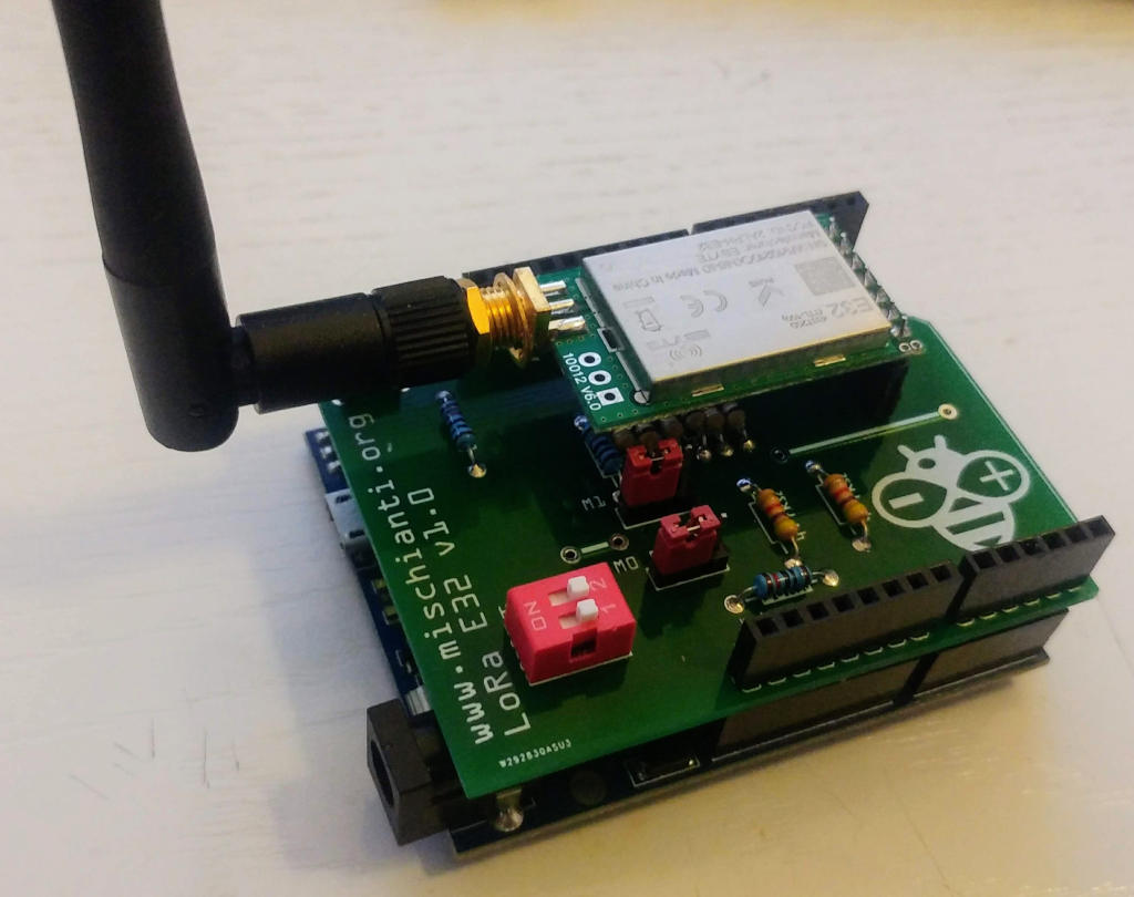
You can order the PCB here
Instruction and assembly video on 6 part of the guide
You can order the PCB here
Instruction and assembly video on 6 part of the guide
I create a library to manage EBYTE E22 series of LoRa device, very powerfull, simple and cheap device.
LoRa or Long Range wireless data telemetry is a technology pioneered by Semtech that operates at a lower frequency than NRF24L01 (433 MHz, 868 MHz or 916 MHz agains 2.4 GHz for the NRF24L01) but at thrice the distance (from 4000m to 10000m).
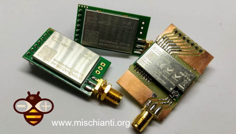
LoRa E22
You can find here AliExpress (433MHz 4Km) - AliExpress (433MHz 10Km)
Please refer to my article to get updated Schema
You can find my library here.
To download.
Click the DOWNLOADS button in the top right corner, rename the uncompressed folder LoRa_E22.
Check that the LoRa_E22 folder contains LoRa_E22.cpp and LoRa_E22.h.
Place the LoRa_E22 library folder your /libraries/ folder.
You may need to create the libraries subfolder if its your first library.
Restart the IDE.

E22
| Pin No. | Pin item | Pin direction | Pin application |
|---|---|---|---|
| 1 | M0 | Input(weak pull-up) | Work with M1 & decide the four operating modes.Floating is not allowed, can be ground. |
| 2 | M1 | Input(weak pull-up) | Work with M0 & decide the four operating modes.Floating is not allowed, can be ground. |
| 3 | RXD | Input | TTL UART inputs, connects to external (MCU, PC) TXD outputpin. Can be configured as open-drain or pull-up input. |
| 4 | TXD | Output | TTL UART outputs, connects to external RXD (MCU, PC) inputpin. Can be configured as open-drain or push-pull output |
5 | AUX | Output | Per indicare lo stato di funzionamento del modulo e riattivare l’MCU esterno. Durante la procedura di inizializzazione di autocontrollo, il pin emette una bassa tensione. Può essere configurato come uscita open-drain o output push-pull (è consentito non metterlo a terra, ma se hai problemi, ad esempio ti si freeze il dispositivo è preferibile mettere una restistenza di pull-up da 4.7k o meglio collegarlo al dispositivo). |
| 6 | VCC | Power supply 2.3V~5.5V DC | |
| 7 | GND | Ground |
As you can see you can set various modes via M0 and M1 pins.
| Mode | M1 | M0 | Explanation |
|---|---|---|---|
| Normal | 0 | 0 | UART and wireless channel are open, transparent transmission is on (Supports configuration over air via special command) |
| WOR Mode | 0 | 1 | Can be defined as WOR transmitter and WOR receiver |
| Configuration mode | 1 | 0 | Users can access the register through the serial port to control the working state of the module |
| Deep sleep mode | 1 | 1 | Sleep mode |
As you can see there are some pins that can be use in a static way, but If you connect It to the library you gain in performance and you can control all mode via software, but we are going to explain better next.
As I already say It’s not important to connect all pin to the output of microcontroller, you can put M0 and M1 pins to HIGH or LOW to get desidered configuration, and if you don’t connect AUX the library set a reasonable delay to be sure that the operation is complete.
When transmitting data can be used to wake up external MCU and return HIGH on data transfer finish.
LoRa E22 AUX Pin on transmission
When receiving AUX going LOW and return HIGH when buffer is empty.

LoRa e22 AUX pin on reception
It’s also used for self checking to restore normal operation (on power-on and sleep/program mode).
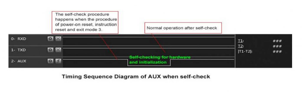
LoRa e22 AUX pin on self-check
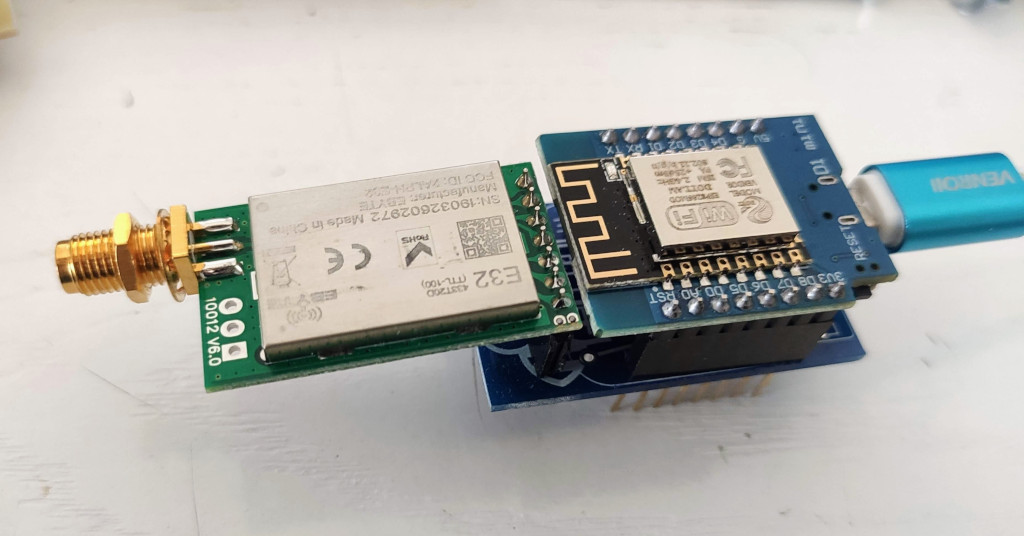
esp8266 connection schema is more simple because It work at the same voltage of logical communications (3.3v).
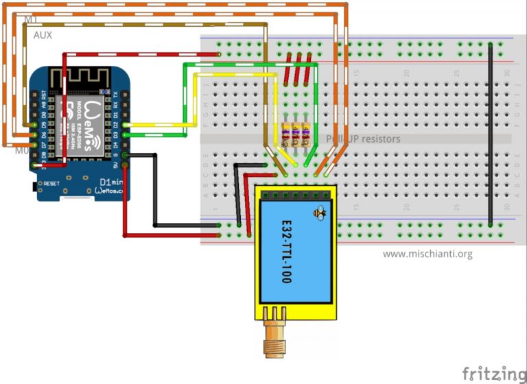
LoRa E22 TTL 100 Wemos D1 fully connected
It’s important to add pull-up resistor (4,7Kohm) to get good stability.
| E22 | esp8266 |
|---|---|
| M0 | D7 |
| M1 | D6 |
| TX | PIN D2 (PullUP 4,7KΩ) |
| RX | PIN D3 (PullUP 4,7KΩ) |
| AUX | PIN D5 (PullUP 4,7KΩ) |
| VCC | 5V (but work with less power in 3.3v) |
| GND | GND |
Similar connection schema for esp32, but for RX and TX we use RX2 and TX2, because by default esp32 doesn’t have SoftwareSerial but have 3 Serial.
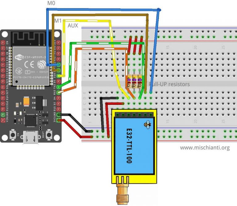
Ebyte LoRa E22 device esp32 dev kit v1 breadboard full connection
| E22 | esp32 |
|---|---|
| M0 | D21 |
| M1 | D19 |
| TX | PIN RX2 (PullUP 4,7KΩ) |
| RX | PIN TX3 (PullUP 4,7KΩ) |
| AUX | PIN D18 (PullUP 4,7KΩ) |
| VCC | 5V (but work with less power in 3.3v) |
| GND | GND |
Arduino working voltage is 5v, so we need to add a voltage divider on RX pin M0 and M1 of LoRa module to prevent damage, you can get more information here Voltage divider: calculator and application.
You can use a 2Kohm resistor to GND and 1Kohm from signal than put together on RX.

LoRa E22 TTL 100 Arduino fully connected
| M0 | 7 (voltage divider) |
| M1 | 6 (voltage divider) |
| TX | PIN 2 (PullUP 4,7KΩ) |
| RX | PIN 3 (PullUP 4,7KΩ & Voltage divider) |
| AUX | PIN 5 (PullUP 4,7KΩ) |
| VCC | 5V |
| GND | GND |
I made a set of quite numerous constructors, because we can have more options and situations to manage.
LoRa_E22(byte rxPin, byte txPin, UART_BPS_RATE bpsRate = UART_BPS_RATE_9600);

LoRa_E22(byte rxPin, byte txPin, byte auxPin, UART_BPS_RATE bpsRate = UART_BPS_RATE_9600);

LoRa_E22(byte rxPin, byte txPin, byte auxPin, byte m0Pin, byte m1Pin, UART_BPS_RATE bpsRate = UART_BPS_RATE_9600);
First set of constructor are create to delegate the manage of Serial and other pins to the library.
txE22pinandrxE22pinis the pin to connect to UART and they are mandatory.auxPinis a pin that check the operation, transmission and receiving status (we are going to explain better next), that pin It isn’t mandatory, if you don’t set It I apply a delay to permit the operation to complete itself (with latency, if you have trouble, like freeze device, you must put a pull-up 4.7k resistor or better connect to the device ).m0pinandm1Pinare the pins to change operation MODE (see the table upper), I think this pins in “production” are going to connect directly HIGH or LOW, but for test they are usefully to be managed by the library.bpsRateis the boudrate of SoftwareSerial normally is 9600 (the only baud rate in programmin/sleep mode)
A simple example is
#include "LoRa_E22.h"
LoRa_E22 e22ttl100(2, 3); // RX, TX
// LoRa_E22 e22ttl100(2, 3, 5, 6, 7); // RX, TX
We can use directly a SoftwareSerial with another constructor
LoRa_E22(HardwareSerial* serial, UART_BPS_RATE bpsRate = UART_BPS_RATE_9600);
LoRa_E22(HardwareSerial* serial, byte auxPin, UART_BPS_RATE bpsRate = UART_BPS_RATE_9600);
LoRa_E22(HardwareSerial* serial, byte auxPin, byte m0Pin, byte m1Pin, UART_BPS_RATE bpsRate = UART_BPS_RATE_9600);
The example upper with this constructor can be do like so.
#include <SoftwareSerial.h>
#include "LoRa_E22.h"
SoftwareSerial mySerial(2, 3); // RX, TX
LoRa_E22 e22ttl100(mySerial);
// LoRa_E22 e22ttl100(&mySerial, 5, 7, 6);The last set of constructor is to permit to use an HardwareSerial instead of SoftwareSerial.
LoRa_E22(SoftwareSerial* serial, UART_BPS_RATE bpsRate = UART_BPS_RATE_9600);
LoRa_E22(SoftwareSerial* serial, byte auxPin, UART_BPS_RATE bpsRate = UART_BPS_RATE_9600);
LoRa_E22(SoftwareSerial* serial, byte auxPin, byte m0Pin, byte m1Pin, UART_BPS_RATE bpsRate = UART_BPS_RATE_9600);The begin command is used to startup Serial and pins in input and output mode.
void begin();in execution is
// Startup all pins and UART
e22ttl100.begin();There a set of methods for manage configuration and get information of the device.
ResponseStructContainer getConfiguration();
ResponseStatus setConfiguration(Configuration configuration, PROGRAM_COMMAND saveType = WRITE_CFG_PWR_DWN_LOSE);
ResponseStructContainer getModuleInformation();
void printParameters(struct Configuration configuration);To simplify the manage of response I create a set of container, for me very usefully to manage errors and return generic data.
This is a status container and have 2 simple entry point, with this you can get the status code and the description of status code
Serial.println(c.getResponseDescription()); // Description of code
Serial.println(c.code); // 1 if Success
The code are
E22_SUCCESS = 1,
ERR_E22_UNKNOWN,
ERR_E22_NOT_SUPPORT,
ERR_E22_NOT_IMPLEMENT,
ERR_E22_NOT_INITIAL,
ERR_E22_INVALID_PARAM,
ERR_E22_DATA_SIZE_NOT_MATCH,
ERR_E22_BUF_TOO_SMALL,
ERR_E22_TIMEOUT,
ERR_E22_HARDWARE,
ERR_E22_HEAD_NOT_RECOGNIZEDThis container is created to manage String response and have 2 entry point.
data with the string returned from message and status an instance of RepsonseStatus.
ResponseContainer rs = e22ttl.receiveMessage();
String message = rs.data;
Serial.println(rs.status.getResponseDescription());
Serial.println(message);This is the more “complex” container, I use this to manage structure, It has the same entry point of ResponseContainer but data is a void pointer to manage complex structure.
ResponseStructContainer c;
c = e22ttl100.getConfiguration();
// It's important get configuration pointer before all other operation
Configuration configuration = *(Configuration*) c.data;
Serial.println(c.status.getResponseDescription());
Serial.println(c.status.code);
c.close();The first method is getConfiguration, you can use It to retrive all data stored on device.
ResponseStructContainer getConfiguration();Here an usage example.
ResponseStructContainer c;
c = e22ttl100.getConfiguration();
// It's important get configuration pointer before all other operation
Configuration configuration = *(Configuration*) c.data;
Serial.println(c.status.getResponseDescription());
Serial.println(c.status.code);
Serial.println(configuration.SPED.getUARTBaudRate());
c.close();
Structure of configuration have all data of settings, and I add a series of function to get all description of single data.
configuration.ADDL = 0x03; // First part of address
configuration.ADDH = 0x00; // Second part
configuration.NETID = 0x00; // NETID used for repeater function

configuration.CHAN = 23; // Communication channel

configuration.SPED.uartBaudRate = UART_BPS_9600; // Serial baud rate
configuration.SPED.airDataRate = AIR_DATA_RATE_010_24; // Air baud rate
configuration.SPED.uartParity = MODE_00_8N1; // Parity bit

configuration.OPTION.subPacketSetting = SPS_240_00; // Packet size
configuration.OPTION.RSSIAmbientNoise = RSSI_AMBIENT_NOISE_DISABLED; // Need to send special command
configuration.OPTION.transmissionPower = POWER_22; // Device power

configuration.TRANSMISSION_MODE.enableRSSI = RSSI_DISABLED; // Enable RSSI info
configuration.TRANSMISSION_MODE.fixedTransmission = FT_TRANSPARENT_TRANSMISSION; // Transmission type
configuration.TRANSMISSION_MODE.enableRepeater = REPEATER_DISABLED; // Enable repeater mode
configuration.TRANSMISSION_MODE.enableLBT = LBT_DISABLED; // Check interference
configuration.TRANSMISSION_MODE.WORTransceiverControl = WOR_RECEIVER; // Enable WOR mode
configuration.TRANSMISSION_MODE.WORPeriod = WOR_2000_011; // WOR timing
You have the equivalent function to get all description:
DEBUG_PRINT(F("HEAD : "));  DEBUG_PRINT(configuration.COMMAND, HEX);DEBUG_PRINT(" ");DEBUG_PRINT(configuration.STARTING_ADDRESS, HEX);DEBUG_PRINT(" ");DEBUG_PRINTLN(configuration.LENGHT, HEX);
DEBUG_PRINTLN(F(" "));
DEBUG_PRINT(F("AddH : "));  DEBUG_PRINTLN(configuration.ADDH, HEX);
DEBUG_PRINT(F("AddL : "));  DEBUG_PRINTLN(configuration.ADDL, HEX);
DEBUG_PRINT(F("NetID : "));  DEBUG_PRINTLN(configuration.NETID, HEX);
DEBUG_PRINTLN(F(" "));
DEBUG_PRINT(F("Chan : "));  DEBUG_PRINT(configuration.CHAN, DEC); DEBUG_PRINT(" -> "); DEBUG_PRINTLN(configuration.getChannelDescription());
DEBUG_PRINTLN(F(" "));
DEBUG_PRINT(F("SpeedParityBit     : "));  DEBUG_PRINT(configuration.SPED.uartParity, BIN);DEBUG_PRINT(" -> "); DEBUG_PRINTLN(configuration.SPED.getUARTParityDescription());
DEBUG_PRINT(F("SpeedUARTDatte     : "));  DEBUG_PRINT(configuration.SPED.uartBaudRate, BIN);DEBUG_PRINT(" -> "); DEBUG_PRINTLN(configuration.SPED.getUARTBaudRateDescription());
DEBUG_PRINT(F("SpeedAirDataRate   : "));  DEBUG_PRINT(configuration.SPED.airDataRate, BIN);DEBUG_PRINT(" -> "); DEBUG_PRINTLN(configuration.SPED.getAirDataRateDescription());
DEBUG_PRINTLN(F(" "));
DEBUG_PRINT(F("OptionSubPacketSett: "));  DEBUG_PRINT(configuration.OPTION.subPacketSetting, BIN);DEBUG_PRINT(" -> "); DEBUG_PRINTLN(configuration.OPTION.getSubPacketSetting());
DEBUG_PRINT(F("OptionTranPower    : "));  DEBUG_PRINT(configuration.OPTION.transmissionPower, BIN);DEBUG_PRINT(" -> "); DEBUG_PRINTLN(configuration.OPTION.getTransmissionPowerDescription());
DEBUG_PRINT(F("OptionRSSIAmbientNo: "));  DEBUG_PRINT(configuration.OPTION.RSSIAmbientNoise, BIN);DEBUG_PRINT(" -> "); DEBUG_PRINTLN(configuration.OPTION.getRSSIAmbientNoiseEnable());
DEBUG_PRINTLN(F(" "));
DEBUG_PRINT(F("TransModeWORPeriod : "));  DEBUG_PRINT(configuration.TRANSMISSION_MODE.WORPeriod, BIN);DEBUG_PRINT(" -> "); DEBUG_PRINTLN(configuration.TRANSMISSION_MODE.getWORPeriodByParamsDescription());
DEBUG_PRINT(F("TransModeTransContr: "));  DEBUG_PRINT(configuration.TRANSMISSION_MODE.WORTransceiverControl, BIN);DEBUG_PRINT(" -> "); DEBUG_PRINTLN(configuration.TRANSMISSION_MODE.getWORTransceiverControlDescription());
DEBUG_PRINT(F("TransModeEnableLBT : "));  DEBUG_PRINT(configuration.TRANSMISSION_MODE.enableLBT, BIN);DEBUG_PRINT(" -> "); DEBUG_PRINTLN(configuration.TRANSMISSION_MODE.getLBTEnableByteDescription());
DEBUG_PRINT(F("TransModeEnableRSSI: "));  DEBUG_PRINT(configuration.TRANSMISSION_MODE.enableRSSI, BIN);DEBUG_PRINT(" -> "); DEBUG_PRINTLN(configuration.TRANSMISSION_MODE.getRSSIEnableByteDescription());
DEBUG_PRINT(F("TransModeEnabRepeat: "));  DEBUG_PRINT(configuration.TRANSMISSION_MODE.enableRepeater, BIN);DEBUG_PRINT(" -> "); DEBUG_PRINTLN(configuration.TRANSMISSION_MODE.getRepeaterModeEnableByteDescription());
DEBUG_PRINT(F("TransModeFixedTrans: "));  DEBUG_PRINT(configuration.TRANSMISSION_MODE.fixedTransmission, BIN);DEBUG_PRINT(" -> "); DEBUG_PRINTLN(configuration.TRANSMISSION_MODE.getFixedTransmissionDescription());
At same way setConfiguration want a configuration strucutre, so I think the better way to manage configuration is to retrieve the current one, apply the only change you need and set It again.
ResponseStatus setConfiguration(Configuration configuration, PROGRAM_COMMAND saveType = WRITE_CFG_PWR_DWN_LOSE);configuration is the strucutre previsiouly show, saveType permit to you to choiche if the change become permanently of only for the current session.
ResponseStructContainer c;
c = e32ttl100.getConfiguration();
// It's important get configuration pointer before all other operation
Configuration configuration = *(Configuration*) c.data;
Serial.println(c.status.getResponseDescription());
Serial.println(c.status.code);

printParameters(configuration);
configuration.ADDL = 0x03; // First part of address
configuration.ADDH = 0x00; // Second part
configuration.NETID = 0x00; // NETID used for repeater function

configuration.CHAN = 23; // Communication channel

configuration.SPED.uartBaudRate = UART_BPS_9600; // Serial baud rate
configuration.SPED.airDataRate = AIR_DATA_RATE_010_24; // Air baud rate
configuration.SPED.uartParity = MODE_00_8N1; // Parity bit

configuration.OPTION.subPacketSetting = SPS_240_00; // Packet size
configuration.OPTION.RSSIAmbientNoise = RSSI_AMBIENT_NOISE_DISABLED; // Need to send special command
configuration.OPTION.transmissionPower = POWER_22; // Device power

configuration.TRANSMISSION_MODE.enableRSSI = RSSI_DISABLED; // Enable RSSI info
configuration.TRANSMISSION_MODE.fixedTransmission = FT_TRANSPARENT_TRANSMISSION; // Transmission type
configuration.TRANSMISSION_MODE.enableRepeater = REPEATER_DISABLED; // Enable repeater mode
configuration.TRANSMISSION_MODE.enableLBT = LBT_DISABLED; // Check interference
configuration.TRANSMISSION_MODE.WORTransceiverControl = WOR_RECEIVER; // Enable WOR mode
configuration.TRANSMISSION_MODE.WORPeriod = WOR_2000_011; // WOR timing

// Set configuration changed and set to not hold the configuration
ResponseStatus rs = e32ttl100.setConfiguration(configuration, WRITE_CFG_PWR_DWN_LOSE);
Serial.println(rs.getResponseDescription());
Serial.println(rs.code);
printParameters(configuration);
c.close()
The parameter all all managed as constant:
| ADDH | High address byte of module (the default 00H) | 00H-FFH |
| ADDL | Low address byte of module (the default 00H) | 00H-FFH |
| SPED | Information about data rate parity bit and Air data rate | |
| CHAN | Communication channel(410M + CHAN*1M), default 17H (433MHz), valid only for 433MHz device chek below to check the correct frequency of your device | 00H-1FH |
| OPTION | Type of transmission, packet size, allow special message | |
| TRANSMISSION_MODE | A lot of parameter that specify the transmission modality |
OPTION
Type of transmission, pull-up settings, wake-up time, FEC, Transmission power
UART Parity bit: UART mode can be different between communication parties
| 4 | 3 | UART parity bit | Constant value |
| 0 | 0 | 8N1 (default) | MODE_00_8N1 |
| 0 | 1 | 8O1 | MODE_01_8O1 |
| 1 | 0 | 8 E1 | MODE_10_8E1 |
| 1 | 1 | 8N1 (equal to 00) | MODE_11_8N1 |
UART baud rate: UART baud rate can be different between communication parties, The UART baud rate has nothing to do with wireless transmission parameters & won’t affect the wireless transmit / receive features.
| 7 | 6 | 5 | TTL UART baud rate(bps) | Constant value |
| 0 | 0 | 0 | 1200 | UART_BPS_1200 |
| 0 | 0 | 1 | 2400 | UART_BPS_2400 |
| 0 | 1 | 0 | 4800 | UART_BPS_4800 |
| 0 | 1 | 1 | 9600 (default) | UART_BPS_9600 |
| 1 | 0 | 0 | 19200 | UART_BPS_19200 |
| 1 | 0 | 1 | 38400 | UART_BPS_38400 |
| 1 | 1 | 0 | 57600 | UART_BPS_57600 |
| 1 | 1 | 1 | 115200 | UART_BPS_115200 |
Air data rate: The lower the air data rate, the longer the transmitting distance, better anti- interference performance and longer transmitting time, The air data rate must keep the same for both communication parties.
| 2 | 1 | 0 | Air data rate(bps) | Constant value |
| 0 | 0 | 0 | 0.3k | AIR_DATA_RATE_000_03 |
| 0 | 0 | 1 | 1.2k | AIR_DATA_RATE_001_12 |
| 0 | 1 | 0 | 2.4k (default) | AIR_DATA_RATE_010_24 |
| 0 | 1 | 1 | 4.8k | AIR_DATA_RATE_011_48 |
| 1 | 0 | 0 | 9.6k | AIR_DATA_RATE_100_96 |
| 1 | 0 | 1 | 19.2k | AIR_DATA_RATE_101_192 |
| 1 | 1 | 0 | 38.4k | AIR_DATA_RATE_110_384 |
| 1 | 1 | 1 | 62.5k | AIR_DATA_RATE_111_625 |
####Sub packet setting
This is the max lenght of the packet.
When the data is smaller than the sub packet length, the serial output of the receiving end is an uninterrupted continuous output. When the data is larger than the sub packet length, the receiving end serial port will output the sub packet.
| 7 | 6 | Packet size | Constant value |
| 0 | 0 | 240bytes (default) | SPS_240_00 |
| 0 | 1 | 128bytes | SPS_128_01 |
| 1 | 0 | 64bytes | SPS_064_10 |
| 1 | 1 | 32bytes | SPS_032_11 |
####RSSI Ambient noise enable
This command can enable/disable the management type of RSSI, It’s important to manage the remote configuration, pay attention isn’t the RSSI parameter in the message.
When enabled, the C0 C1 C2 C3 command can be sent in the transmitting mode or WOR transmitting mode to read the register. Register 0x00: Current ambient noise rssi Register 0X01: rssi when the data was received last time.
| 5 | RSSI Ambient noise enable | Constant value |
| 0 | Enable | RSSI_AMBIENT_NOISE_ENABLED |
| 1 | Disable (default) | RSSI_AMBIENT_NOISE_DISABLED |
####Transmission power
You can change this set of constant by apply a define like so:
#define E22_22 // default value without set
#define E22_30
You can configure Channel frequency olso with this define:
// One of

#define FREQUENCY_433
#define FREQUENCY_170
#define FREQUENCY_470
#define FREQUENCY_868
#define FREQUENCY_915####Enable RSSI
When enabled, the module receives wireless data and it will follow an RSSI strength byte after output via the serial port TXD
####Transmission type
Transmission mode: in fixed transmission mode, the first three bytes of each user’s data frame can be used as high/low address and channel. The module changes its address and channel when transmit. And it will revert to original setting after complete the process.
####Enable repeater function
####Monitor data before transmission
When enabled, wireless data will be monitored before it is transmitted, which can avoid interference to a certain extent, but may cause data delay.
####WOR
WOR transmitter: the module receiving and transmitting functions are turned on, and a wake-up code is added when transmitting data. Receiving is turned on.
WOR receiver: the module is unable to transmit data and works in WOR monitoring mode. The monitoring period is as follows (WOR cycle), which can save a lot of power.
####WOR cycle
If WOR is transmitting: after the WOR receiver receives the wireless data and outputs it through the serial port, it will wait for 1000ms before entering the WOR again. Users can input the serial port data and return it via the wireless during this period. Each serial byte will be refreshed for 1000ms. Users must transmit the first byte within 1000ms.
- Period T = (1 + WOR) * 500ms, maximum 4000ms, minimum 500ms
- The longer the WOR monitoring interval period, the lower the average power consumption, but the greater the data delay
- Both the transmitter and the receiver must be the same (very important).
First we must introduce a simple but usefully method to check if something is in the receiving buffer
int available();It’s simply return how many bytes you have in the current stream.
Normal/Transparent transmission mode is used to send messages to all device with same address and channel.
LoRa E22 transmitting scenarios, lines are channels
There are a lot of method to send/receive message, we are going to explain in detail:
ResponseStatus sendMessage(const String message);ResponseContainer receiveMessage();First method is sendMessage and is used to send a String to a device in Normal mode.
ResponseStatus rs = e22ttl.sendMessage("Prova");
Serial.println(rs.getResponseDescription());
The other device simply do on the loop
if (e22ttl.available() > 1){
ResponseContainer rs = e22ttl.receiveMessage();
String message = rs.data;` `// First ever get the data
Serial.println(rs.status.getResponseDescription());
Serial.println(message);
}If you want send a complex strucuture you can use this method
ResponseStatus sendMessage(const void *message, const uint8_t size);

ResponseStructContainer receiveMessage(const uint8_t size);
It’s used to send strucutre, for example:
struct Messaggione {

char type[5];

char message[8];

bool mitico;

};

struct Messaggione messaggione = {"TEMP", "Peple", true};

ResponseStatus rs = e22ttl.sendMessage(&messaggione, sizeof(Messaggione));

Serial.println(rs.getResponseDescription());
and the other side you can receive the message so
ResponseStructContainer rsc = e22ttl.receiveMessage(sizeof(Messaggione));

struct Messaggione messaggione = *(Messaggione*) rsc.data;

Serial.println(messaggione.message);

Serial.println(messaggione.mitico);If you want read first part of the message to manage more type of strucutre you can use this method.
ResponseContainer receiveInitialMessage(const uint8_t size);I create It to receive a string with type or other to identify the strucuture to load.
struct Messaggione { // Partial strucutre without type

char message[8];

bool mitico;

};

char type[5]; // first part of structure

ResponseContainer rs = e22ttl.receiveInitialMessage(sizeof(type));

// Put string in a char array (not needed)

memcpy ( type, rs.data.c_str(), sizeof(type) );

Serial.println("READ TYPE: ");

Serial.println(rs.status.getResponseDescription());

Serial.println(type);

// Read the rest of structure

ResponseStructContainer rsc = e22ttl.receiveMessage(sizeof(Messaggione));

struct Messaggione messaggione = *(Messaggione*) rsc.data;At same manner I create a set of method to use with fixed transmission
You need to change only the sending method, because the destination device don’t receive the preamble with Address and Channel.
So for String message you have
ResponseStatus sendFixedMessage(byte ADDL, byte ADDH, byte CHAN, const String message);

ResponseStatus sendBroadcastFixedMessage(byte CHAN, const String message);
and for structure you have
ResponseStatus sendFixedMessage(byte ADDL, byte ADDH, byte CHAN, const void *message, const uint8_t size);

ResponseStatus sendBroadcastFixedMessage(byte CHAN, const void *message, const uint8_t size );
Here a simple example
ResponseStatus rs = e22ttl.sendFixedMessage(0, 0, 0x17, &messaggione, sizeof(Messaggione));

// ResponseStatus rs = e22ttl.sendFixedMessage(0, 0, 0x17, "Ciao");
Fixed transmission have more scenarios
LoRa E22 transmitting scenarios, lines are channels
If you send to a specific device (second scenarios Fixed transmission) you must add ADDL, ADDH and CHAN to identify It directly.
ResponseStatus rs = e22ttl.sendFixedMessage(2, 2, 0x17, "Message to a device");If you want send a message to all device in a specified Channel you can use this method.
ResponseStatus rs = e22ttl.sendBroadcastFixedMessage(0x17, "Message to a devices of a channel");If you want receive all broadcast message in the network you must set your ADDH and ADDL with BROADCAST_ADDRESS.
ResponseStructContainer c;

c = e22ttl100.getConfiguration();

// It's important get configuration pointer before all other operation

Configuration configuration = *(Configuration*) c.data;

Serial.println(c.status.getResponseDescription());

Serial.println(c.status.code);

printParameters(configuration);

configuration.ADDL = BROADCAST_ADDRESS;

configuration.ADDH = BROADCAST_ADDRESS;

// Set configuration changed and set to not hold the configuration

ResponseStatus rs = e22ttl100.setConfiguration(configuration, WRITE_CFG_PWR_DWN_LOSE);

Serial.println(rs.getResponseDescription());

Serial.println(rs.code);

printParameters(configuration);
c.close();
###Wireless configuration
This device support wireless configuration with sepecial command, but seems not work, i ask to EBYTE but no response received.
I implement a command that send the packet in the correct way (tested with logic analizer) but seems not work.
By the way, first you muset activate RSSI noise environment, than you can use the command like so:
    Configuration configuration;

  configuration.ADDL = 0x13;
  configuration.ADDH = 0x13;
  configuration.NETID = 0x00;

  configuration.CHAN = 23;

  configuration.SPED.uartBaudRate = UART_BPS_9600;
  configuration.SPED.airDataRate = AIR_DATA_RATE_010_24;
  configuration.SPED.uartParity = MODE_00_8N1;

  configuration.OPTION.subPacketSetting = SPS_240_00;
  configuration.OPTION.RSSIAmbientNoise = RSSI_AMBIENT_NOISE_DISABLED;
  configuration.OPTION.transmissionPower = POWER_22;

  configuration.TRANSMISSION_MODE.enableRSSI = RSSI_DISABLED;
  configuration.TRANSMISSION_MODE.fixedTransmission = FT_FIXED_TRANSMISSION;
  configuration.TRANSMISSION_MODE.enableRepeater = REPEATER_DISABLED;
  configuration.TRANSMISSION_MODE.enableLBT = LBT_DISABLED;
  configuration.TRANSMISSION_MODE.WORTransceiverControl = WOR_TRANSMITTER;
configuration.TRANSMISSION_MODE.WORPeriod = WOR_2000_011;Now you have all information to do your work, but I think It’s important to show some realistic examples to undestand better all the possibility.
-
Ebyte LoRa E22 device for Arduino, esp32 or esp8266: settings and basic usage
-
Ebyte LoRa E22 device for Arduino, esp32 or esp8266: library
-
Ebyte LoRa E22 device for Arduino, esp32 or esp8266: configuration
-
Ebyte LoRa E22 device for Arduino, esp32 or esp8266: fixed transmission and RSSI
-
Ebyte LoRa E22 device for Arduino, esp32 or esp8266: power saving and sending structured data
-
Ebyte LoRa E22 device for Arduino, esp32 or esp8266: repeater mode and remote settings
-
Ebyte LoRa E22 device for Arduino, esp32 or esp8266: WOR microcontroller and Arduino shield
-
Ebyte LoRa E22 device for Arduino, esp32 or esp8266: WOR microcontroller and WeMos D1 shield
-
Ebyte LoRa E22 device for Arduino, esp32 or esp8266: WOR microcontroller and esp32 dev v1 shield