
The goals / steps of this project are the following:
- Compute the camera calibration matrix and distortion coefficients given a set of chessboard images.
- Apply a distortion correction to raw images.
- Use color transforms, gradients, etc., to create a thresholded binary image.
- Apply a perspective transform to rectify binary image ("birds-eye view").
- Detect lane pixels and fit to find the lane boundary.
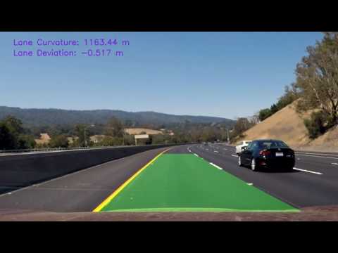
- Determine the curvature of the lane and vehicle position with respect to center.
- Warp the detected lane boundaries back onto the original image.
- Output visual display of the lane boundaries and numerical estimation of lane curvature and vehicle position.
Video file is available here.
All source code can be viewed in the python notebook file AdvancedLaneFinding.ipynb or in python source here.
I start by preparing "object points", which will be the (x, y, z) coordinates of the chessboard corners in the world. Here I am assuming the chessboard is fixed on the (x, y) plane at z=0, such that the object points are the same for each calibration image. Thus, objp is just a replicated array of coordinates, and objpoints will be appended with a copy of it every time I successfully detect all chessboard corners in a test image. imgpoints will be appended with the (x, y) pixel position of each of the corners in the image plane with each successful chessboard detection.
I then used the output objpoints and imgpoints to compute the camera calibration and distortion coefficients using the cv2.calibrateCamera() function. I applied this distortion correction to the test image using the cv2.undistort() function and obtained this result:

Example above.
The source image was converted to HLS, RGB, and YUV color spaces. Various threshold values were hand-tuned to select just a portion of the image that would contribute to finding lane pixels.
The first row shows the result of the color space conversion. The second row shows the resulting mask from selecting pixels at a certain threshold.

The first row shows the result of the color space conversion. The second row shows the resulting mask from selecting pixels at a certain threshold.

The first row shows the result of the color space conversion. The second row shows the resulting mask from selecting pixels at a certain threshold.

I developed a custom convolutional kernel to attempt to directly detect right sloping diagonal lines. This is derived from the standard Sobel filter for X and Y edge gradients. The kernel was flipped horizontally to detect left sloping edges.

Here are examples of resulting masks:

An experiment to use Sobel gradients did not result in useful information, and was ultimately discarded. Here's an example of that filter.

Individual masks were thresholded to a floating point image where each pixel was either 0 or 0.1. Then the masks were added together and all pixels with two or more contributions were used. Here the full image is shown without the region of interest applied.

A custom polygon was created to exclude pixels outside the road.

A perspective transform was used to rectify the binary image. This attempts to transform pixels in the source image to remove the effects of camera perspective such that parallel lines in the world result in parallel image lines.
To accomplish this, a custom polygon was chosen which matched the lane lines in the perspective view. Then a second polygon was chosen as the destination space. This was more rectangular, but not perfectly so. The OpenCV function cv2.getPerspectiveTransform() was used to calculate the matrix. And cv2.warpPerspective() was used to apply the matrix to the image.

I created a histogram of pixels at each column of the image. Then the two largest regions to the right and left of centerline were taken as the starting lane positions.

This histogram was moved in progressive bounding boxes up the image. The bounding box was adjusted to the center of the detected lane position. This gives it continuity. When no pixels are found, the box simply advances up. Here's the example of the binary mask and resulting walk of the image showing the bounding boxes at each step.

Repeated runs can use the existing curves as search region for the next, and don't need to repeat entire image histogram, which can speed results and aid in continuity.
A second order polynomial in the Y axis was fit to the resulting lane points using numpy.polyfit. Here's an image displaying the resulting curve overlayed over the binary mask.

The resulting curves were transformed back into the original image space using the inverse of the matrix which went to linear space. Then the curved green polygon was overlayed over the original lane image. Here are three results:


The curves were transform from pixel space to world space using assumed lane width of 3.7 m and view distance polygon of 20 m. This curve was sampled at the bottom edge closest to the car at both lane lines. The curvature was taken as the derivative of the curve function at that point, and the values averaged to determine a radius.
The deviation, or lane position, was calculated by using the same pixel to world space transform. It assumed the camera was mounted at the center of the car, and thus determined the center X offset from the lane positions.
Here's an example showing lane info and curvature overlay:

The different color spaces each afforded unique information in determining lane line pixels. Ultimately, this technique succeeded only when much time was spent hand-tuning thresholds for the target video, and failed to abstract well to new situations with different lighting conditions, more desaturated lane lines, additional phantom cracks, or extreme lane curvature.
The inverse perspective transform was quite successful at creating a linear space for lane determination, but assumes a level road and needs additional parameters to handle slopes.
I enjoyed creating the custom convolutional kernel, and it was quite powerful at targeting strong image features such as long continuous diagonals. These are the kind of kernels that are learned automatically via deep learning techniques using convolutional layers. I attempted to create a semantic segmentation artificial neural network to detect lane line pixels, but ran out of time. I used my Unity simulator to create perfectly annotated images.

I then tried two different approaches, here and here, to semantic segmentation. These were quite large networks that required enormous amounts of time to train. I ran these overnight on AWS EC2 K80 P2 Large instances. Each time the resulting image was not segmented at all. Due to time constraints, I will continue this on my own time.


